Hi I'm considering constructing one of these DAC boards + Optical to I2S converter (Opus WM8804) in the same 1U project box (1U high, 10 inches deep), however.
I need it ALL to run from 12v-13.5v DC (Float SLA voltage) as I would like to use it in a mobile studio setup and I like to have my equipment run from a DC UPS system. So, wasting as little amount of power as possible on capacitors and linear regulators would be ideal. Also noise is an issue...
Can I get some suggestions on what to use for a DC-DC converter which would be suitable for the dac?
Btw I've tried finding the schematic in the thread, but the link is dead?
Also, seeing as I'm super-poor I was hoping for a cheap buffer stage kit too, any suggestions on what to use for that? Transistor is fine, though a starved heater buffer stage would be nice.
I should also add that I do not have much experience with DAC's, however I can build complex kits within an hour or so, I feel confident in tackling this project, its just that budget and enclosure constraints are limited.
Last edited:
Red Baron connection to Tube-I-Zator
Hi everyone.
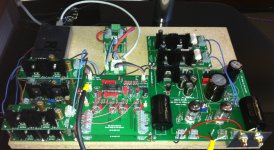
I'm finishing up the Red Baron dac board. I'm already running the Tube-I-zator (latest version and the 1st generation dac board).
I'm not installing the MOSFET Buffer I/V stage parts, and I see from the pictures that the signal out is then taken from the (L/R) Master/Slave output next to the TDA1541A dac chip on the Red Baron board. Doesn't this need a ref (or ground) as well , or am I not seeing something?
Could it be that the REF is taken from under the Red Baron board to the Tube-I-zator?
Thanks,
Chris
Hi everyone.
I'm finishing up the Red Baron dac board. I'm already running the Tube-I-zator (latest version and the 1st generation dac board).
I'm not installing the MOSFET Buffer I/V stage parts, and I see from the pictures that the signal out is then taken from the (L/R) Master/Slave output next to the TDA1541A dac chip on the Red Baron board. Doesn't this need a ref (or ground) as well , or am I not seeing something?
Could it be that the REF is taken from under the Red Baron board to the Tube-I-zator?
Thanks,
Chris
Hi Chris,
look here to my grounding scheme:
An externally hosted image should be here but it was not working when we last tested it.
If you connect it like this with a star GND, you could use the GND of the Tube-i-Zator for the RCA-GND connction.
I hope this answer your question.

The screen from the main transformer should connect with a very short lead to the main enclosing metal box (Faraday cage), not a long lead to the star ground (Main Audio Ground).
I don't understand why each regulator has a separated power supply wire from the return supply wire. Surely the flow and return of each regulator should be a twisted pair into the part of the DAC that consumes current.
Note also that all the wires feeding current have no return route associated with them. They must all be circuits and MUST have a flow and return. Showing anything less is confusing.
Last edited:
Hi Oliver
Looks like your DAC didnt have any change now
this is the perfect time to start solder
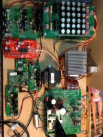
BTW i just have Tubeizator, DAC, shunt & hv (no need supply pcb)
what is the other pcb i need to complete this ?
(i saw a little pcb in the middle of your big picture)
btw BOM this DAC can not see again (look blur) in this thread
maybe you need to attach them
Best regards
Looks like your DAC didnt have any change now
this is the perfect time to start solder
BTW i just have Tubeizator, DAC, shunt & hv (no need supply pcb)
what is the other pcb i need to complete this ?
(i saw a little pcb in the middle of your big picture)
btw BOM this DAC can not see again (look blur) in this thread
maybe you need to attach them
Best regards
Attachments
Hi Oliver
Looks like your DAC didnt have any change now
this is the perfect time to start solder
BTW i just have Tubeizator, DAC, shunt & hv (no need supply pcb)
what is the other pcb i need to complete this ?
(i saw a little pcb in the middle of your big picture)
btw BOM this DAC can not see again (look blur) in this thread
maybe you need to attach them
Best regards
Hi Pocoyo,
the small pcb above the DAC V2.3 is the I2S switch (USB/SPDIF).
All BOM´s you will find in my blog HERE.
Hi Pocoyo,
the small pcb above the DAC V2.3 is the I2S switch (USB/SPDIF).
All BOM´s you will find in my blog HERE.
Hi Oliver
I think i will build your dac with simple structure (No Need USB)
can i connect the digital input / RCA to TDA 1541 PCB ?
so the pcb we need (pls corect me if something missing)
1. PSU Pcb
2. Shunt Reg PCB
3. Shunt Reg +5v PCB (optional)
4. TDA 1541 PCB
5. HV Shunt Reg PCB
6. Tube i zator PCB
7. ??? (what for)
Thank you Oliver, best regards
Hi Pocoyo,
my DAC has a I2S input. If you want to use a Digital RCA (S/PDIF) input you need two additional pcb´s.
1st the S/PDIF to I2S converter, e.g. the Twisted Pear S/PDIF Tranceiver Module
2nd my UHS-Buffer Module
It looks like here:
An externally hosted image should be here but it was not working when we last tested it.
An externally hosted image should be here but it was not working when we last tested it.
An externally hosted image should be here but it was not working when we last tested it.
Last edited:
just asking before buying
is that right tda1541 use 12pcs x 0.22uf wima ?
if i look in the other structure they used 0.022 uf
looks like i need to buy from you
- 2 pcs UHSB, still got in the stock ?
btw
- i didnt look you use I2S switch pcb what happen ?
- as u give a bigger tda1541 pcb, is that ok if i cut the
pcb below " master / slave " ? any distortion later ?
( i need a little pcb, so easier to put into 1 chassis )
- if i look in page 48 there is mods ssr from 5v to 3.3v
what for the mods ?
best regards
btw
- i didnt look you use I2S switch pcb what happen ?
- as u give a bigger tda1541 pcb, is that ok if i cut the
pcb below " master / slave " ? any distortion later ?
( i need a little pcb, so easier to put into 1 chassis )
- if i look in page 48 there is mods ssr from 5v to 3.3v
what for the mods ?
i got the answer on page 50
- i2s switch for other signal input maybe for i pad
- i can cut the board it will be green baron
- mods for uhsb from ecsdesign / john brown

Help needed.....
Hello everyone.
I've owned this DAC for a long time and enjoy it very much...thanks Oliver! I've also recently added The Red Baron board...even better. I utilize the Teralink X2 (no clock mods - I can't microsolder, but I did do the 5V and 3.3V shunt mods)
My original build is posted #571.
The "digital landscape" is changing rapidly and I'm starting to try new/different USB to I2S converters. I recently purchased this one in I2S output:
http://www.diyaudio.com/forums/digi...nous-usb-i2s-spdif-converter-24bit-96khz.html
My problem is that the output is faint music covered with a veil of static and hiss. The creator of the board has been extremely responsive and helpful, but he doesn't understand the dac chip like the folks here. I know there are no problems with the DAC board, as I reconnected the X2 and everything was back to normal. You can't see the I2S connections, as they're under the board, but I've rechecked multiple times and they're correct. I think I'm missing something silly here.....
Input welcome....
I'm attaching a picture of the build (and yes, that's a Barbie...long story)
Attachments
Hi Crobinns5421,
How was the sound before the Red Baron? Any noise at full volume with no music playing? The reason I ask is, I too upgraded to the Red Baron, and now I
have some sort of ground loop making the unit inoperable. I'm in the process of trying to quite this thing down.
Where is your star ground point? I don't see it in the picture.
Ned
Oliver (and everyone),
I looked at your system picture, but I couldn"t tell where you had the following grounded:
1. 5V High Speed Buffer
2. USB Isolator
3. Digital Power on Red Baron
4.USB to I2S Converter
Thanks!
Hi Chris,
1. High Speed Buffer GND to +5V Shunt GND
2. USB Isolator GND to +5V Shunt GND
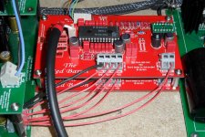
3. You could use only one (Analog/Digital) GND of the Red Baron, because they are star grounded on the pcb. Connect the GND to the TDA1541A Shunt GND. (see attached photo)
4. USB to I2S Converter GND to +5V Shunt GND
I hope this helps! BTW, i will dispatch your two ordered add. UHS-Buffer tomorrow.
Attachments
- Status
- This old topic is closed. If you want to reopen this topic, contact a moderator using the "Report Post" button.
- Home
- Group Buys
- "Reference" TDA1541A DAC with I2S-BUS architecture