is that two dollars and quite a few cents, or two thousand six hundred and seventy five dollars (=$2675)?$ 2.675
is that two dollars and quite a few cents, or two thousand six hundred and seventy five dollars (=$2675)?

$ 2675 (two thousand six hundred and seventy five dollars)

Hi,Could be flux build up that wasn't cleaned after soldering.
If anyone is interested in some fully built salas shunt regs on olivers pcbs, I have a few that are surplus here. Pm if interested ;-)
Built Salas Shunt Regs - DVB-Projekt PCBs - diyAudio


Can you inform me the items left to sell and prices to be delivered to Tenerife, Canary Islands, Spain.
Regards,
Jorge
Hi Oliver, all,
Apologies if this has been answered already.. Eyes getting blurry from the long discussions!
I understand the Red Baron input attenuators is designed for 5v TTL, can it be modified to accept the 3.3v output from the WM8805 directly? This eliminates the need for buffers?
Cheers, Colin
Apologies if this has been answered already.. Eyes getting blurry from the long discussions!
I understand the Red Baron input attenuators is designed for 5v TTL, can it be modified to accept the 3.3v output from the WM8805 directly? This eliminates the need for buffers?
Cheers, Colin
Hi Oliver, all,
Apologies if this has been answered already.. Eyes getting blurry from the long discussions!
I understand the Red Baron input attenuators is designed for 5v TTL, can it be modified to accept the 3.3v output from the WM8805 directly? This eliminates the need for buffers?
Cheers, Colin
Hi Colin,
the only way is to use the buffer module.
Best regards,
Oliver
I never got the attenuators to work with 3.3v from both WM8805 and CDpro2... I ended up discarding the attenuators and use simple grid stoppers...
Correct me if Im wrong, but isnt that the attenuators are to avoid saturating the TDA1541 input? In that case, direct drive with 3.3v should not be a problem?
Correct me if Im wrong, but isnt that the attenuators are to avoid saturating the TDA1541 input? In that case, direct drive with 3.3v should not be a problem?
Oliver, remind me again why that is? Because of the flipflop?
Because one would think that the attennuators would work on 3.3v as well (with lower value resistors).
You could read all about the I2S att. circuit in -ecdesigns- tread HERE.
I never got the attenuators to work with 3.3v from both WM8805 and CDpro2... I ended up discarding the attenuators and use simple grid stoppers...
Correct me if Im wrong, but isnt that the attenuators are to avoid saturating the TDA1541 input? In that case, direct drive with 3.3v should not be a problem?
I had the same problem with my USB to I2S converter. With my UHS Buffer in-between everything works perfect.
Hi Oliver,
I just recieved my Red Baron pcb a couple of weeks back.Do I have to still do the leg change on the output devices or has the board layout changed?
cheers
Paul
Hi Paul,
if you would like to use the onboard I/V you must do the leg change, yes!
Cannot set to 0v
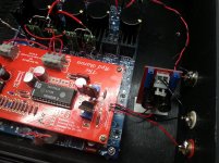
I am having trouble setting any of the test points to 0 volts ( either the ones on the red Baron board or the ones for setting dc bias on reference board for audio output.
All I get is around -8vdc and very little adjustment...I have checked all the earth grounding and it seems ok...could it be some sort of ground float issue?.
I did originally have the 74hc02 in the wrong way , but corrected it.
The i2s signals come from the cs8414 on the board below.
Is it ok to have only 1 +5vdc supply for the Red Baron?
cheers
Paul
Attachments
Got my board working beautifully with the buffer.. I guess its something about the current drive of TTL vs CMOS... the 'zen' in me is still a bit anal about removing the buffers BUT.. this already beats the 'simple' circuits out there by miles.
One thing i noticed, I usually had to use 2nd/3rd order analog filtering. But with the recent board, a simple capacitor bypass to ground is sufficient, the image doesnt get bloated.
Thanks to all for the knowledge sharing!
One thing i noticed, I usually had to use 2nd/3rd order analog filtering. But with the recent board, a simple capacitor bypass to ground is sufficient, the image doesnt get bloated.
Thanks to all for the knowledge sharing!
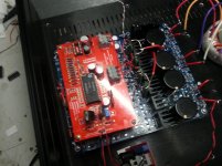
I now have mine working too.
I had to connect the i2s from the cs8414 to the tda1541 directly...but even then, when it was making music there was still clicking in the sound. It wasnt until I tied the - ( negative) of the spdif before it entered the cs8414, to common ground. After that all was nice and quiet.
Sounds VERY good, although the gain seems to be low?.
It wasnt until I tied the - ( negative) of the spdif before it entered the cs8414, to common ground. After that all was nice and quiet.
Sounds VERY good, although the gain seems to be low?.
Hi Chilli6565,
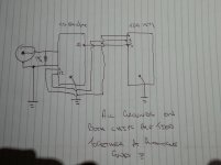
Any chance you can post a sketch of this? I'm not a 100% sure I understand
what you've done.
Ned
Hi Chilli6565,
Any chance you can post a sketch of this? I'm not a 100% sure I understand
what you've done.
Ned
I will try and do something today and take some better pics to help explain
Hi Chilli6565,
Any chance you can post a sketch of this? I'm not a 100% sure I understand
what you've done.
Ned
Hope this simplistic diagram helps.
I dont know why it worked in my situation, but unitl I grounded the earth/ground of the spdif it didnt work properly.
Normally I have the earth/ground of the spdif floating ?..also I dont use isolation transformer in spdif input.
Attachments
- Status
- This old topic is closed. If you want to reopen this topic, contact a moderator using the "Report Post" button.
- Home
- Group Buys
- "Reference" TDA1541A DAC with I2S-BUS architecture