Well after many months of planning and building I've finally finished, and I must say it sounds absolutely stunning. This is the closest I've come to reproducing the sound of quality vinyl.
I couldn't have done it without the help of you Oliver, you're the best!
There is one problem I'm having. When the unit is sitting idle, and the preamp is turned up to full volume, there is a fairly loud hum/hiss. This is not normal for my system, it is normally dead quite.
If anyone can give me suggestions of how to eliminate this noise I would appreciate it.
I will be posting some finished photo's very soon. I tried earlier, but I encountered an upload problem.

Ned
I couldn't have done it without the help of you Oliver, you're the best!
There is one problem I'm having. When the unit is sitting idle, and the preamp is turned up to full volume, there is a fairly loud hum/hiss. This is not normal for my system, it is normally dead quite.
If anyone can give me suggestions of how to eliminate this noise I would appreciate it.
I will be posting some finished photo's very soon. I tried earlier, but I encountered an upload problem.
Ned
Well after many months of planning and building I've finally finished, and I must say it sounds absolutely stunning. This is the closest I've come to reproducing the sound of quality vinyl.
I couldn't have done it without the help of you Oliver, you're the best!
There is one problem I'm having. When the unit is sitting idle, and the preamp is turned up to full volume, there is a fairly loud hum/hiss. This is not normal for my system, it is normally dead quite.
If anyone can give me suggestions of how to eliminate this noise I would appreciate it.
I will be posting some finished photo's very soon. I tried earlier, but I encountered an upload problem.
Ned
Did you check for 0DC offset on the output ?
Hi Regal,
Look's like that's probably my problem. I thought I checked it, but I guess I didn't.
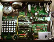
With the unit connected to a cd transport, from a cold start, I get 12vdc. As it warms up it gradually settles down to a varying 275-300mv, both channels the same, and it's not steady. The voltage constantly climbs and drops.
I'm using Russian K75-10's bypassed with FT-3's for the output caps, when I put my finger on the outer case the hum gets very loud.
I tried uploading photo's again, but it still won't let me.
Look's like that's probably my problem. I thought I checked it, but I guess I didn't.
With the unit connected to a cd transport, from a cold start, I get 12vdc. As it warms up it gradually settles down to a varying 275-300mv, both channels the same, and it's not steady. The voltage constantly climbs and drops.
I'm using Russian K75-10's bypassed with FT-3's for the output caps, when I put my finger on the outer case the hum gets very loud.
I tried uploading photo's again, but it still won't let me.
Two things,
I figured that the mk7 design isn't really correct as far as allowing DC coupling. Sounds like you are using output caps which is good, but configuring the correctoutput signal ground needs some re-work, I just ordered my PCB so probably not much help but.
Your caps can't be having 275-300mV DC on the output of the cap, my guess is you are using the wrong ground for the output. Check it against a true ground (I would use your preamp rca input signal ground as a self check)
The other thing when you have got truly 0VDC on your output you may still find you need to grind some paint off the russian caps, many of us have found the these caps need to have their cases anchored (solder a wire from the case of the cap to star ground.)
many of us have found the these caps need to have their cases anchored (solder a wire from the case of the cap to star ground.)
I was actually thinking of doing this in the past.
Thanks for the input.

Hi everyone,
i'm looking at a complete DIY DAC kit for my squeezebox duet at an affordable price, am i at the right place?
from the first page, i just saw PCB, is this GroupBuy also providing the whole components, the setup plans, etc?
If i'm not in the right place, my appologies, can you redirect me to the right one please?
thank you in advance
Hi Ton,
if you want to use two Red Baron DAC´s parallel with the onboard I/V stage, you must connect it like this:
1st - Every DAC module needs all parts of the I/V stage, expect the I/V resistors. Adjust the DAC output to 0V (DC-offset of the TDA1541A).
An externally hosted image should be here but it was not working when we last tested it.
Don´t forget to make the small modification and switch the source and drain of the MOSFET like in this picture !!!
An externally hosted image should be here but it was not working when we last tested it.
2nd - The output of the current buffers on each DAC module (inner four-sided point of the I/V resistor) must be connected together (parallel).
An externally hosted image should be here but it was not working when we last tested it.
3rd - You need only one pair of I/V resistors with 250R value on one DAC module (four-sided / round point).
4th - You connect the DC-Reference Module as followed:
From DAC module
Ref. (Audio out) --> Ref. +5V
GND (DC Digital) --> GND
From DC Ref. Module
GND Ref. Left --> GND RCA Left
GND Ref. Right --> GND RAC Right
You could see it on this photo
An externally hosted image should be here but it was not working when we last tested it.
5th - Trimm the RCA GND to 0V
An externally hosted image should be here but it was not working when we last tested it.
That´s it.
Cheers
Wouldn't it be easier and offer much less risk to just take the audio output from the top of the I/V resistor (red baron's L or R) thru a Coupling cap and use normal ground?
Your alternative scheme gives a lifted ground to the amplifier, although only ~4V, it still isn't good practice IMHO.
Bargain Sale
Because i need space for the next generation of my DAC,
you could order my ready build DAC module V2.2 with direct input modification
for the special price of
$40 each
An externally hosted image should be here but it was not working when we last tested it.
Worldwide shipping: $ 9
paypal fee: 3,9%
If you are interested, please send me a PM.
The last one is sold!
Wouldn't it be easier and offer much less risk to just take the audio output from the top of the I/V resistor (red baron's L or R) thru a Coupling cap and use normal ground?
Your alternative scheme gives a lifted ground to the amplifier, although only ~4V, it still isn't good practice IMHO.
If you want to use the onboard Grounded-Gate MOSFET Current Buffer I/V Stage (-ecdesigns- MK7 version) with two Red Barons parallel, you must connect it as described.
The descripion is from -ecdesigns- because i asked John this question in the planning stage of the Red Baron DAC module
")

Usage of two parallel Red Baron DAC´s with onboard MK7 I/V stage
Here is what John (ecdesigns) said about paralleling his MK7 I/V stage:
Wouldn't it be easier and offer much less risk to just take the audio output from the top of the I/V resistor (red baron's L or R) thru a Coupling cap and use normal ground?
Your alternative scheme gives a lifted ground to the amplifier, although only ~4V, it still isn't good practice IMHO.
Here is what John (ecdesigns) said about paralleling his MK7 I/V stage:
-ecdesigns- said:Use separate decoupling caps for each chip.
Use separate DEM clock injector circuit for each chip (they can share the same clock source).
Use separate I2S attenuators for each chip.
Duplicate the current buffer circuit for the second DAC and only connect the drains of both MOSFETs together.
You also have to reduce I/V resistor value to 250 Ohms (250 Ohm output impedance)
Here is what John (ecdesigns) said about paralleling his MK7 I/V stage:
Thanks I ddin't mean paralelling, just using one output, unless you can trim the current thru the I/V resistor to be put you right at 0V on the output I would think a coupling cap is in order.
I haven't experimented with mine been waiting on a new batch of bib Salas regs, looks like it is going to be a long one. Do you have the any of your Salas reg board left ?
I haven't experimented with mine been waiting on a new batch of bib Salas regs, looks like it is going to be a long one. Do you have the any of your Salas reg board left ?
All my Salas reg modules are in stock!
Personal announcement
Well my friends it is time again to say thanks to all of you, who like and ordered my pcb´s.
Because i am no developer of electronic circuits but have the knowledge to design pcb´s,
i wanted to give something back to the community.
Since i started with my 1st pcb, the Optical-Volume-Control on 15th October 2009,
a small donation from every sold pcb goes to diyaudio.com
Today i am proud to say that your cumulated donation achieve
$ 2.675
Keep on having fun with my pcb´s and best regards
Oliver
Because i am no developer of electronic circuits but have the knowledge to design pcb´s,
i wanted to give something back to the community.
Since i started with my 1st pcb, the Optical-Volume-Control on 15th October 2009,
a small donation from every sold pcb goes to diyaudio.com
Today i am proud to say that your
cumulated donation achieve $ 2.675 Keep on having fun with my pcb´s and best regards
Oliver
- Status
- This old topic is closed. If you want to reopen this topic, contact a moderator using the "Report Post" button.
- Home
- Group Buys
- "Reference" TDA1541A DAC with I2S-BUS architecture