Oliver,
Will my DC coupled B1 buffer powered by a Salas shunt reg work as an output stage? It is a unity gain, impedance correcting buffer based on 2SK170s. It would be positioned in the pre-amp, the next box down from the DAC in my system.
If so, what do I really need to build a DAC with USB and optical inputs?
1. A teralink converter,
2. A Power supply board,
3. Main Shunt reg board
4. DAC module board
Is that it, discounting box, components etc.?
Many thanks
Lucas
Hi Lucas,
i am building the DCB1 blue version at the moment
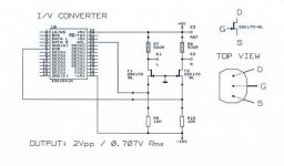
Additional you need an I/V output stage e.g. like my Tube-I-zator module or the new I/V stage from ecdesigns (see attached picture). The DCB1 comes after this stage.
So you need:
2x +/- Power Supply Modules (+5V, -5V, -15V)
1x TDA1541A shunt module
1x I/V output stage
1x Teralink X2 module (only USB input)
1x SPDIF to I2S module e.g. from Twisted Pear Audio with additional Toslink module
Best regards,
Oliver
Attachments
Hi Lucas,
i am building the DCB1 blue version at the moment
Additional you need an I/V output stage e.g. like my Tube-I-zator module or the new I/V stage from ecdesigns (see attached picture). The DCB1 comes after this stage.
So you need:
2x +/- Power Supply Modules (+5V, -5V, -15V)
1x TDA1541A shunt module
1x I/V output stage
1x Teralink X2 module (only USB input)
1x SPDIF to I2S module e.g. from Twisted Pear Audio with additional Toslink module
Best regards,
Oliver
Do you mean that I need 2 of your power supply boards, or does one board contain both?
Do you mean that I need 2 of your power supply boards, or does one board contain both?
You need two board´s because you have minimum three voltages.
If you would like to add a 2nd +5V line for additional parts (USB to I2S ect.),
you could use the last line of the 2nd board.
Best regards,
Oliver
Hi Oliver,
the transistor 2SK170BL matched ? In this case I don't need matched correct ?
Regards
Francesco.
Hi Francesco,
yes correct.

Yes Oliver, I have MUR 1520 onhand , and waiting MUR860 on the way ... on MUR820 I must buy 5 and multiply ,10,15 ..etc in farnell . thanks.
For the regs, the MUR860 or 820 are much of a muchness. Nothing in it really.
For those who want to build this DAC and don´t have a TDA1541A DAC chip,
ebay seller cusackmusic sells new NOS ones
HERE
I've just bought the very last one he had listed! The listing said he had bought 450 of them, and that 433 were sold. The other 17, who knows....but the listing is over now.
I'm assembling parts for this design pending arrival of the PCBs but can't readily source the Kiwame 220K, 5W resistors. I can get 200R and 240R. Would either be an acceptable substitute?
Neither can I find and 270uF 16VW Sanyo OsCon caps. Can anyone recommend a UK distributor without the usual min. order penalties?
Apologies for any trouble and thanks in advance . . .
Neither can I find and 270uF 16VW Sanyo OsCon caps. Can anyone recommend a UK distributor without the usual min. order penalties?
Apologies for any trouble and thanks in advance . . .
Sanyo OsCon caps are low ESR, and can easily be substituted with the equally excellent Panasonic FM low ESR caps, available everywhere.
Last edited:
I'm assembling parts for this design pending arrival of the PCBs but can't readily source the Kiwame 220K, 5W resistors. I can get 200R and 240R. Would either be an acceptable substitute?
You could use any 5W resistor with a value around 220K for the bleeder resistor.
If you use a smaller value, the caps discharge a bit quicker if you power off.
Hificollective have the 200K and 240K in stock.
Best,
Oliver
An excellent replacement for the SEPC, for anybody that can't source them. Farnell UK, but they are US stock, so best for people to buy direct from Farnell US really.
Bear in mind that they are only rated at 10v.
UNITED CHEMI-CON|APSA100ELL271MHB5S|CAPACITOR ALUM POLYMER 270UF, | Farnell United Kingdom
Bear in mind that they are only rated at 10v.
UNITED CHEMI-CON|APSA100ELL271MHB5S|CAPACITOR ALUM POLYMER 270UF, | Farnell United Kingdom
- Status
- This old topic is closed. If you want to reopen this topic, contact a moderator using the "Report Post" button.
- Home
- Group Buys
- "Reference" TDA1541A DAC with I2S-BUS architecture
