Hi Folks,
I'm an electronic enthusiast who spend a lot of time building audio equipment. I found that to many diyers one of the hurdles is to get a reasonably priced dedicated pcb for their projects. Using proto boards is fine but it is clumsy, time consuming and prone to error. Very often the projects were shelved when half done. Money and time were spent without a result. I experienced the same obstacle until a pcb layout software (Eagle 5.9 full version) was bought. That is to say, I can make my own pcbs and build an equipment without much headache. Since then I have the intention to make small quantity dedicated pcbs, such as pre, power amps and active xover etc..., to share with diyers in the forum, at cost. If you come across any exciting audio circuits please let me know. I am more than happy to design a board and share with anyone interested in building one for their own. Pricing will be very reasonable. For example, a 6" x 4" FR-4 (glass fiber epoxy) double-side board should cost less than USD9.00. Shipping fee is also very inexpensive : about USD2.00 within the US and USD3.00 for Europe. Please join me and post your favorite circuits. You have no obligation to buy. My goal is to bring the fun of building audio equipment to diyers.
circuitscc
This is a pre-amp suggested by one member.
The values are preliminary.
Please feel free to make suggestions.
The values are preliminary.
Please feel free to make suggestions.
An externally hosted image should be here but it was not working when we last tested it.
Sorry, you said well. The bride of zen:
http://www.passdiy.com/pdf/brideofzen.pdf
I think the support isn´t a problem, but the demand will be few. Is a nice and cheap but old project.
I need only two or three pcbs.
http://www.passdiy.com/pdf/brideofzen.pdf
I think the support isn´t a problem, but the demand will be few. Is a nice and cheap but old project.
I need only two or three pcbs.
Last edited:
After I have digested R. Slone's OptiMos it's apparent that almost all of the transistors have to be matched properly with their counter parts in order to get a good result.
In the mean time, I'm reviewing his book : Hi-Power Amp Construction Manual. I'll come back once a compromise between complexity and cost is established.
Thanks for your input.
In the mean time, I'm reviewing his book : Hi-Power Amp Construction Manual. I'll come back once a compromise between complexity and cost is established.
Thanks for your input.
The preferred choice of FETs are 2SK147/2SJ369 or 2SK170/2SJ74 but they are expensive and difficult to get. Fairchild J112/J175 are much cheaper. They are suitable substitues.
I will start the board design and post it soon.
yes but whos design is this, and whats it called?
This line amp can be modified to become a HEADPHONE AMP. The output stage was in increased to 4 pairs while an extra pair of FETs Q6 ad Q8 were connected in parallel to Q5 and Q7 respectively in the VAS stage to provide extra drive.
When it is used as a line amp Q6 /Q8, Q11/Q15 and Q12/Q16 with the associated resistors can be omitted and their locations on the pcb will be left blank.
Regulated +/-15V is provided by LM317, LM337 (not shown the schematic) and associated filter caps, have been integrated to the same circuit board. Each assembled circuit board will form a fully functional and independent channel. It will take 2 identical boards for a stereo setup.
The final circuit and board designed of this all-FET line/headphone amp are presented in the attached pdf files.
Please post your comments.
Attachments
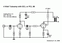
Hi id like to design a pcb for a tube amp. This might be interesting for many tube beginners.
The schematic was already posted her by a diy member but is very popular in germany. Plese see attachment. Stereo would be fine and the pot should be on the pcb. best regards Thorsten
The schematic was already posted her by a diy member but is very popular in germany. Plese see attachment. Stereo would be fine and the pot should be on the pcb. best regards Thorsten
Attachments
Hi circuitscc,
Very nice work. I can see you have put a lot of effort making symbols and components, they really do look good. I'll have to put a bit more effort into mine to lift my game.
Looking at your transistor symbol, I am wondering if the size is forcing you to space the resistors too far apart. On some of my boards I have been surprised how sparse they end up looking in real life.
I don't know about the actual circuit, I've been spending my time appreciating the excellent drafting.
Have you mastered Eagle 3D yet? If not, send me the PCB file and I'll generate a few pretty pictures.
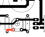
BTW: On the PCB, the lower right pot has one trace not mitered.
regards
Very nice work.
Looking at your transistor symbol, I am wondering if the size is forcing you to space the resistors too far apart. On some of my boards I have been surprised how sparse they end up looking in real life.
I don't know about the actual circuit, I've been spending my time appreciating the excellent drafting.
Have you mastered Eagle 3D yet? If not, send me the PCB file and I'll generate a few pretty pictures.
BTW: On the PCB, the lower right pot has one trace not mitered.
regards
As transistor is the only active device in the circuit I make them a bit bigger than average to emphasize its role.
The pot you mentioned was optional. Some music lovers would like to use the volume control of a CD player. It can be replaced with a jumper.
Please tell me your email address so that I can send you the schematic.
The pot you mentioned was optional. Some music lovers would like to use the volume control of a CD player. It can be replaced with a jumper.
Please tell me your email address so that I can send you the schematic.
As transistor is the only active device in the circuit I make them a bit bigger than average to emphasize its role.
I see. They look good and fit nicely, but can you see how they have made you space the resistors far apart, though it doesn't really matter on this PCB.
The pot you mentioned was optional. Some music lovers would like to use the volume control of a CD player. It can be replaced with a jumper.
See the attachment.
Please tell me your email address so that I can send you the schematic.
Email sent.
regards
Attachments
- Status
- This old topic is closed. If you want to reopen this topic, contact a moderator using the "Report Post" button.
- Home
- Group Buys
- Low Cost PCB Group Buy

