Bought one of those laser thermometers. I am sure it will come in handy a lot over the years.
Uriah
Yeah to measure the concrete...
")
"And it's hotter than concrete
In July in Houston
And it'll get worse here
Before it turns nice"
Lyle Lovett - Flyswatter / Ice Water Blues
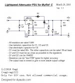
Yeah guys, IS VERY IMPORTANT to isolate the LM338 from the case by using an spacer and a washer. Or you can just be sure the heatsink is not going to become in contact with anything. I still haven't tested the PSU in real world conditions (I mean with a Lightspeed), but it should get a bit hot, so heatsinking is neccesary for sure.
I am thinking about what to do with the LDR turning on and off matter. Maybe someone has a solution for that?
I am thinking about what to do with the LDR turning on and off matter. Maybe someone has a solution for that?
So you uriah, propose to put a big cap AFTER the regulator, is that right? What is the maximum/minimum/normal consumption of a Lightspeed? If consumption is too low and we need only 2 or 3 seconds "maybe" 5000uF is too much. But is a matter of experimenting...
The bigger ones I have at hand are 2x 470uF pana FM
The bigger ones I have at hand are 2x 470uF pana FM
Maximum is 40mA at 5V. Minimum and normal arent to far from each other and are probably around 1mA. I use a far different power supply so I dont think testing mine would show what happens. That why I threw 5000uf out there, simply because it wont be expensive for that cap and it will probably last long enough.
Here is a Nichicon Muse of 10,000uf, small size, good price and will most certainly run for a long time after the amp turns off. If you use this you might consider using the protection diodes in the regulator circuit if you use LM338 or 317.
UFW0J103MHD Nichicon Aluminum Electrolytic Capacitors - Leaded
Andrew, maybe 150.000uF is a bit too killer for an LDR. Appart that taking in account its tolerance, which easily can be -+20%, we are talking of a variation of -+30mF, which is an absolut value of 60.000uF if I am not wrong. An error tolerance of 60.000uF when we are aiming for 5.000uF or 10.000uF seems too far unexact. Or maybe I am wrong in something. I think you should try what happens when using 5kuF, 10kuF or 20kuF.
But that is just my oppinion
Uriah, I will ask you a favour. Could you add my lightspeed psu schematic the protection diode and the big cap? I am asking becase the regulator already has some protection diodes, and I would like to know where will be placed the new diode.
Just for curiosity, how are you Uriah supplying your Lightspeed? It makes me scratch my head thinking how could be this far different PSU
Its a lot different. It uses a VVS, Current Pump and VCS. It lets me change impedance at will so I can listen to the differences. Build An Amp if you want to check it out but I dont share the schematic. Redesigning it as I type Fun stuff.
Andrew is showing that we dont need 5k or 10kuf. He tested at 150uf and found the voltage drop was kind of slow. I think that after 4 or 5 seconds it would start to get loud on 150uF. Well, maybe real loud but it shows that if we up the capacitance to maybe 1000uf it should be fine. Should only cost maybe 30 cents.
I know its crazy but I dont have any schematic software. What have you been using Regi? I just draw and then put it on a pcb.
Fun stuff.Andrew is showing that we dont need 5k or 10kuf. He tested at 150uf and found the voltage drop was kind of slow. I think that after 4 or 5 seconds it would start to get loud on 150uF. Well, maybe real loud but it shows that if we up the capacitance to maybe 1000uf it should be fine. Should only cost maybe 30 cents.
I know its crazy but I dont have any schematic software. What have you been using Regi? I just draw and then put it on a pcb.
No!!!!Andrew is showing that we dont need 5k or 10kuf. He tested at 150uf and found the voltage drop was kind of slow. I think that after 4 or 5 seconds it would start to get loud on 150uF.
0.005F is equal to 5mF is equal to 5000uF is equal to 5000000nF
He calculated from: charge/discharge 1F at 1A and the voltage rises/falls at 1V/s
Last edited:
Hi,
at 1mA of draw for the 4LDRs, 5mF will drop at ~200mV/s
150mF will drop ~400mV/min. I would have to charge it up between every track!
Do the arithmetic.
I guess I thought thats what you were doing.
For drawing my schematics I have been using.....Microsoft Paint! No jokes, I like the way to work in it by copy, paste and draw pixel by pixel. If you take ability on it, it can give you some professional results. Here attached is the schematic.
So finally, after all the calculations, what are the final values acceptable?
No jokes, I like the way to work in it by copy, paste and draw pixel by pixel. If you take ability on it, it can give you some professional results. Here attached is the schematic.So finally, after all the calculations, what are the final values acceptable?
Attachments
- Status
- This old topic is closed. If you want to reopen this topic, contact a moderator using the "Report Post" button.
- Home
- Group Buys
- MyRef_C with Ultimate BOM