Ordered the taller sinks. 6.4W/C should do the trick very well and not leave room for doubt. Of course Avnet didnt get back to me and I had to track them down. By the time I did they were out of the 307 they had in stock this morning.. Had to go to Digikey. If you can believe it Digikey was second least expensive after Avnet. Of course Avnet is enforcing their restocking fee even though if I had been able to order the sinks I wanted this morning from them they would not have charged me, so if they had actually gotten in contact with me in a timely manner I would not have got the fee.... come on people!
Anyway, it sure is a nice day out!!")
Anyway, it sure is a nice day out!!
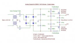
The more I look into the 24V supply for the speaker protection, the more problems I find. Besides too much voltage on the diodes, the value of R14 is too high at 470 Ohms. The attached files are from a LTspice simulation and they show only about 15 volts on the 24V rail. The relay needs at least 18 volts to guarantee switching. In the graph the green curve is the diode voltage, showing 58 volts reverse voltage. The blue curve is the LM3886 V+, about 28 volts from a 22V transformer, and the red curve is the 24V supply, running around 15V. When I build the amplifier, I will measure this circuit carefully to see what needs adjusted to bring it into specification.
Attachments
If it does fit with no problems, I will give it a go. Not that having it hot is a major concern, but for my tastes 94Cº seems a bit on the high side, don't know about what long term effects could it produce...Dang, just deleted my post... anyway.
Bill, what about a 4Ohm load?
The same diodes have been used for quite a while now. How do you calculate your concern?
Spoke to Caddock about a half an hour ago. The engineer agrees with you. Fine with no problems at 5W but 7W would be a problem. We are cutting the bottom fin off of that heatsink so I am guessing about 15W/C and 15C/W is what he and I talked about. This allows for the LM318 to be under it. You only have to cut the left side of the sink. Right can stay as is. So I think that 15C/W would be a good estimation. However.. We could be safe and return those sinks and use this one
Digi-Key - HS104-2-ND (Manufacturer - 504222B00000G)
6.4C/W natural convection. Its pretty close to the same price so it would basically cost me shipping back to them and shipping again to me, but not any kind of deal breaker.
It is almost exactly twice as efficient with the same footprint.
Of course this only comes into play when dumping 100% of the power into your speakers, which would melt my speakers but I suppose some of us might actually play it at full volume for a while.
Uriah
So, if cost is not very high and waiting time neither is, I would try to return them.
BTW, Why don't you go with heatsinks taller than that? We are allowd to use HS with more height that them. We could aim to source heatsinks as tall as 4 or 5cm. We have the space
Last edited:
Man we should all work the heck out of this board this summer. Could be a lot of fun.
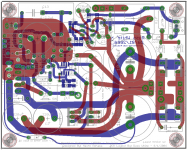
Yes could be funny, this was just an excercise since I've never designed or modified nothing with Eagle.
In an ideal world I would like to make also a FET based PSU for the LM318 and larger use of SMD...
Something like that:
Attachments
Last edited:
I don't think Uriah is changing any value. The fact is that Caddock resistor's maximum power will be defined by the size of the heatsink attached to it. It is not like the usual 0.25W, 1W or 2W resistors, which are factory defined maximum power. So if Mauro said 7W output res., we might try to achieve that with a Caddock, so we must find the optimal heatsink size.Not to start anything but...
Mauro did an expert job with the original design and parts specification (values and tolerances). Why is there any discussion of "will this dissipate enough"?
I guess I lost sync when the conversation went from changing "brands" of the parts to changing "values" of those parts.
Appart from that, the higher the rated power for a resistor, the colder it will work, that meaning a longer life for the component.
BTW, anyone knows what are the differences between "current sense resistors" and plain resistors? If there is any...
Uriah, Thos obbligatos and pcb boards are very nice
Guys,
I am embarassed to admit that I made a mistake on my BOM. The Caddock I used is not MP2060, but MP930, which is rated for 30 watts and a lot cheaper. It is in a TO-220 package. That has proven to be completely reliable after months of continuous use. Lesson learned: check records, and don't rely on memory.
The resistor presently selected for the kit is somewhat smaller, with less surface area for dissipation and heatsink contact, in a TO-126 package. I hope all these calculations and suppositions are correct and the smaller resistor is adequate.
The heatsink issue is troubling. I chose that particular sink because it is compact and had a decent rating. The alternative chosen by Uriah APPEARS to be more efficient but is actually slightly smaller. I am not an expert on heatsinks, but I think the rating appears a bit optimistic. How can it be so much more efficient, yet smaller? Perhaps it is more massive, with thicker material. I'm not sure how the TO-126 package will fit into it. I guess you can always use a heatsink for a larger package with a smaller resistor, but not the other way around, so it should be okay if a little sloppy.
Peace,
Tom E
T0-126 package could be the MP915 with a 15W rating [again...depending on heatsink]. Perfectly adequate. The slightly smaller body of the resistor and corresponding heatsink even give more compactness, which seems to be desireable on these boards as well.
Great price and for a group buy on a 100 or so is certainly an excellent choice. I think Uriah did VERY well on the selection that also kept the total kit price damb reasonable, especially considering the Obbligatos.
My first chip amp LM4780 has Caddocks MK132 and upright soldier mounted Rikkens. Sounds awesome! Making a physically big resistor fight a tight space is something I learned right out of the gate...
Mounting Note: Mount on a smooth, clean, and flat heat sink surface with a thermal interface material, such as thermal grease. The entire exposed ceramic portion must be in thermal contact with the heat sink. When screw mounting, use a compression washer which provides a mounting force of 150 to 300 pounds (665 to
1330 N). This will provide sufficient pressure on the package over time and through large temperature varia-
tions to maintain the maximum power dissipation capability. Mounting torque to avoid package damage is 8
in-lbs. (0.90 N-m). If a spring clip is used, a clip force of 8 to 30 pounds (35 to 130 N) is recommended to be
applied to the center of the package. The clip should be round or smooth in the contact area to avoid concen-
trating the load on a small point of the plastic body of the package. Another mounting option is to use a
pressure bar method which can achieve a greater mounting force with a greater contact area.
For additional applications information regarding mounting and pulse handling see the Caddock
Applications Notes at caddock.com or contact Applications Engineering
Last edited:
Bill_P talking about 1N4001 diodes led me to think about them particularly about the recovery characteristics of such diodes.
We spent money on MUR820 diodes for their ultra fast/soft recovery (less HF pollution) but in the same power lines we use 1N4001 standard diodes...
Uriah, do you think is possible to swap the two 1N4001 with other diodes?
If so SBYV27-100 are very good candidates (I've used them a lot of times with good results), relatively cheap and with higher specs than 1N4001.
The Mouser code is 625-SBYV27-100-E3/4
Bill_P talking about 1N4001 diodes led me to think about them particularly about the recovery characteristics of such diodes.
We spent money on MUR820 diodes for their ultra fast/soft recovery (less HF pollution) but in the same power lines we use 1N4001 standard diodes...
Uriah, do you think is possible to swap the two 1N4001 with other diodes?
If so SBYV27-100 are very good candidates (I've used them a lot of times with good results), relatively cheap and with higher specs than 1N4001.
The Mouser code is 625-SBYV27-100-E3/4
Uriah,
You could check if we might be able to fit a pair of MUR820 where the 1N4001 are. Although I don't think it will make any difference, because they are no supplying anything in the siignal path. What are your thoughts, guys?
Uriah,
You could check if we might be able to fit a pair of MUR820 where the 1N4001 are. Although I don't think it will make any difference, because they are no supplying anything in the siignal path.
MUR820s costs are twice...
Sure the rectified voltage is not used in the signal path but they are fed (and pollute) by the same AC1 and AC2 lines.
The HF noise injected in power lines then passes to the amp PSU...
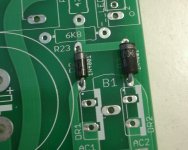
SBYV27-100 is good electrically but it is larger than the 1N4001 so it would need to be checked for proper fit in the board.
SBYV27-100 are a perfect fit:
Attachments
Guys, how about fuses? Don't see that in the BOM, I can see there are several preferences, like stereo, dual mono, one fuse per mono, 120/240v main, etc
I've used one 3.15A slow-blo fuse for this configuration:
- 2x 120VA R-core transformers
- 2x MyRef Boards
- One case with one VDE socket
- 230V mains
I can imagine Uriah cringing every time someone talks about changing parts. I am not expecting him to make changes at this late point in the group buy. The problems I pointed out are for the benefit of those buying their own parts. If you want to change D2 and D3 there are lots of options. The MUR820 is extreme overkill, is expensive, and the leads would have to be formed to fit the hole spacing on the board. Here are some 100 piece prices from Mouser.
1N4001 $0.038 each
1N4002 $0.038 each
UF4002 $0.099 each
MUR120 $0.152 each
SBYV27-100 $0.35 each
MUR820 $0.56 each
Regarding fuses, those are not on the PC board and would not be supplied in the group buy. In my present chip amp there are two 200VA toroids, each fed by a 2A slow blow fuse (120 VAC line).
- Status
- This old topic is closed. If you want to reopen this topic, contact a moderator using the "Report Post" button.
- Home
- Group Buys
- MyRef_C with Ultimate BOM