Uriah,
Thankyou hardly seems adequate for my parcel that arrived today.
A real neat piece of packaging.
Having helped with some (much simpler) mail shots in the past I appreciate the work that went into yours.
You and your helpers have done a fantastic job.
My very grateful thanks.
Tom
Thankyou hardly seems adequate for my parcel that arrived today.
A real neat piece of packaging.
Having helped with some (much simpler) mail shots in the past I appreciate the work that went into yours.
You and your helpers have done a fantastic job.
My very grateful thanks.
Tom
Just checking: is the trafo you have 12V dual secondaries or 24 (or 25)V secondaries, please?
The pics were a bit misleading...
Cheers
Jon
sorry, at first I was asking if 12v series equaling 24v was correct, then I ask about 24v secondaries
and 25v is what I bought.
The only wire I am confused about is PGND, does that get wired from the secondary or from chassis ground?
Last edited:
This is my view on it, but I've never found a simple walkthru about this either, it's just what I've picked up.
PGND isn't part of the traffo secondaries - i.e there is no PGND wire coming from the traffo secondary.
PGND arises once you've connected the traffo secondaries to the bridge or bridges. Once you do that you get, on the output of the bridge(s) one of the following: +V/PGND; +v/-V/PGND. In all cases, as far as I'm concerned, it's the PGND after the bridge that needs to be connected back to earth.
The simplest way of doing this is to take a wire from PGND and connect it to the chassis. Don't forget that safety earth is also connected to the chassis so this means that PGND will earth itself to ground via the safety earth, so long as mechanically the two are connected somehow (i.e, there is a conductive surface contact between safety and PGND earth that will allow any stray current to flow from PGND to safety earth).
So, for the MyRef boards where it says PGND on them you should take a lead from there and connect it to the chassis such that it has a conductive circuit to safety earth.
That's my understanding, but I am a very big novice at this, however safety is something I've looked at a lot and so I'm hoping that my explanation is at least safe, if not ideal. I can live with safe, but not ideal - it means I don't get fried!!!
On your traffo you have normal twin secondaries - don't forget AC current doesn't have positive/ground like DC does, so if you're using both secondaries to wire the two MYRef channels, then PGND doesn't really exist until after you'e put the AC current through the bridges.
Last edited:
PGND isn't part of the traffo secondaries - i.e there is no PGND wire coming from the traffo secondary.
PGND arises once you've connected the traffo secondaries to the bridge or bridges.
...
In all cases, as far as I'm concerned, it's the PGND after the bridge that needs to be connected back to earth.
...
So, for the MyRef boards where it says PGND on them you should take a lead from there and connect it to the chassis such that it has a conductive circuit to safety earth.
Not Exactly...
In this post I've linked an image from Decibel Doungeon web site that clearly illustrates the double secondaries trasfo wiring:
An externally hosted image should be here but it was not working when we last tested it.
The ground in the image is PGND and must be connected to MyREf's PGND, that same PGND should be connected also to chassis/safety earth, better via a ground breaker, like the one Regi took from ESP site:
An externally hosted image should be here but it was not working when we last tested it.
Last edited:
Sorry, edited.
The post you're talking about (DDungeon) is for a traffo with twin primary supplies. I'm talking about a single primary and dual secondary.
But that picture on DDungeon also shows how to connect dual secondaries to just one bridge. My Ref has two bridges, one on each board, so one xecondary goes to one bridge, the other secondary goes to the other bridge.
Last edited:
But that picture on DDungeon also shows how to connect dual secondaries to just one bridge. My Ref has two bridges, one on each board, so one xecondary goes to one bridge, the other secondary goes to the other bridge.
 Noo!
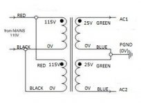
Noo!The image shows how to obtain AC1 (+24V), AC2 (-24V) and PGND (0V)
These tree points must be connected to every MyRef monoblock in case of a single transformer.
It says on Nuuk's site that that connection is for a DUAL secondary connecting to a SINGLE bridge.
Not one half of the secondary connecting to one bridge and the second half of the secondary connecting to anothe bridge.
But, I am talking about 240V traffo's for the uk, and also a traffo that has one primary and dual secondaries to connect up.
Not one half of the secondary connecting to one bridge and the second half of the secondary connecting to anothe bridge.
But, I am talking about 240V traffo's for the uk, and also a traffo that has one primary and dual secondaries to connect up.
Look at http://www.diyaudio.com/forums/audi...al-gainclone-kit-building-instructions-4.html
See the two secondaries connecting to two different bridges.
But that's for a single traffo with one primary and dual secondary
See the two secondaries connecting to two different bridges.
But that's for a single traffo with one primary and dual secondary
See this page, and post 70 in particular
http://www.diyaudio.com/forums/audi...al-gainclone-kit-building-instructions-7.html
And post 77 where he shows the PGND connection going back to safety. Note it's after the traffo has connected to the bridges. http://www.diyaudio.com/forums/audi...al-gainclone-kit-building-instructions-8.html
So is Peter Daniels wrong?
Last edited:
Or we're talking about different things or we're saying the same thing and we don't understand that it's so...
Do we agree that the two AC from the image are AC1 and AC2? (to me it seems so)
I'm saying that the GND from the two secondaries series goes to both PGND on the MyRef and chassis.
If you're sayng that that GND goes to chassis and that PGND goes too to the chassis we're talking about the same thing, it's so?
If not can you precise your point?
Now I understand...
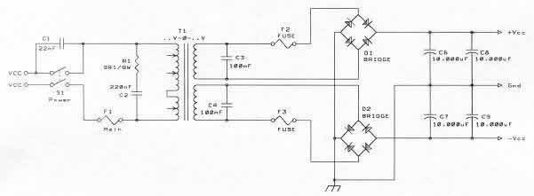
Peter Daniel's posts doesn't apply here because his PSU is using two bridges (one for each semi-wave), like this one:
The MyRef PSU uses a simpler approach, like this one:
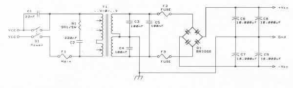
(Images from this TNT-Audio article)
So Peter Daniels is perfectly right but the MyRef PS is wired differently.
Peter Daniel's posts doesn't apply here because his PSU is using two bridges (one for each semi-wave), like this one:
The MyRef PSU uses a simpler approach, like this one:
(Images from this TNT-Audio article)
So Peter Daniels is perfectly right but the MyRef PS is wired differently.
Last edited:
The image shows how to obtain AC1 (+24V), AC2 (-24V) and PGND (0V)
These tree points must be connected to every MyRef monoblock in case of a single transformer.
AHHHHHH! it's getting worse not better LOL! I am just a stupid man,
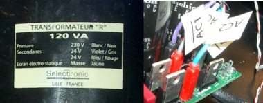
The AN-2225 has two Primary and two secondary windings. knowing that,
What gets wired to AC1, AC2 and PGND please?
What gets wired to AC1, AC2 and PGND please?
It should be like the attachment
Check voltages with a multimeter...
Ignore the +24V and -24V, we're talking about AC, my fault...
Attached also my connection.
Attachments
Last edited:
Wiring the xformer was the most confusing aspect in the last group buy. I can offer this explanation, and hope that it is clear enough for you to avoid electrocution or damage to the new xformer. If you have any doubts, DO NOT PROCEED, and get someone to help you or do it for you.
Both red wires and both black wires are tied together, so you have a pair of blacks and a pair of reds in two bundles. The pair of reds goes to one side of the mains supply, and the black pair goes to the other side of the mains supply. There should be a fuse on one of those legs, right behind the IEC jack, and a power switch right behind that, both in front of the xformer. You can use a single pole switch on only one leg, or a double pole switch for both legs. I prefer switching both legs.
Do NOT attach to mains until you have done the following. Using a voltmeter or a low voltage circuit such as a flashlight bulb and battery, find which of the two blue wires and which of the two green wires are part of the same winding in the secondaries. You must test for continuity. Whichever pair of blue and green wires gives you an open circuit (NO continuity) should be taped together. Check them twice or even three times to be certain. This will be the 0 volt (PGND) leg. The other blue wire and the other green wire will be + and - legs. I don't think it matters which one is plus and which one is minus. The pair of blue and green that do NOT allow current to flow (NO continuity) between them should be joined and attached to PGND.
Many here (and elsewhere) advocate adding a wire to attach PGND to the mains safety ground point in the chassis, along with some circuitry to discourage any flow into the amp instead of to safety ground. That part is up to you, and I'll leave it to the experts to explain it (actually, they already have, and in great detail). The amp will work without such a connection, but it may ultimately compromise your safety in case of a failure inside the amplifier that allows mains current to flow through the amp to metal parts (RCA's, binding posts) that are supposed to be only carrying signal. Since all of those metal parts MUST be isolated (insulated) from the chassis, I'm not sure what form that failure might take, but I guess it is possible and should be taken into account. If you have any doubts, DO NOT PROCEED without the parallel connection of PGND to the mains safety ground.
If you are running both mono amps from the same xformer, that's too bad because you lose one advantage of true monoblock amplification. If you do use a single xformer, all connections to both boards should be identical, using paralleled connections. You'll need to run a pair of wires from each output of the single xformer, with one wire of each pair going to the same point in each amp. If you have any doubts, DO NOT PROCEED.
Peace,
Tom E
luck or lack of it has absolutely nothing to do with safety.luckily I didnt blow anything up
Use a mains bulb tester for every new mains powered project and for every modification of a mains powered project.
PPC,
yes it appears to be getting worse.
They don't understand what each other is trying to explain.
A dual secondary has two secondary windings that are isolated from each other.
This can be wired with a bridge rectifier for each secondary.
That results in two DC supplies that are isolated.
Peter's diagram connects these two isolated DC supplies together. He has called the join Zero Volts. The other two DC connections are +ve supply and -ve supply. The whole thing is thus a dual polarity supply.
A centre tapped secondary has a single winding with an extra tap in the middle of that single winding. This can only feed a single bridge rectifier.
AC1 goes to ~,
AC2 goes to ~,
DC comes from + & -.
The centre tap creates the Zero Volts reference for the + & - DC voltages. This creates a dual polarity supply.
A two secondary can be converted to a centre tapped secondary. It is then wired up exactly as a centre tapped transformer.
A centre tapped transformer cannot be converted to a dual secondary.
Do mix up the two wiring arrangements.
The MyRef uses a centre tapped transformer type of connection.
If you choose to use a dual secondary you must first convert it to centre tapped. Then proceed. It's simple. But still use a mains bulb tester to first power up that newly wired transformer, check. Power off. Connect the rectifier and use the bulb tester. Check. Power off. Connect the amplifier and use the bulb tester. Check.
When you has stopped modifying your wiring and completed all the connecting you need to do, then do one more bulb tester power up and check everything again for correct voltages. Only now can you try starting up your project wired direct to the mains socket outlet. NO LUCK involved.
Be very Careful with Madison ears advice.
He is describing a dual primary wired for 110/120Vac duty.
Madison,
you need a title for your advice.
Some might think you are advising on all voltage type wiring. Do not mislead them.
Last edited:
- Status
- This old topic is closed. If you want to reopen this topic, contact a moderator using the "Report Post" button.
- Home
- Group Buys
- MyRef_C with Ultimate BOM