I went on E-bay.
Please note that the group buys here are not for profit, and often donate to this site to help with expenses. This is not the case for the slugs on ebay who profit from Mr. Pass' generosity. Please refrain from giving them your business. It is unethical and illegal.
Group Buys
Agree, thanks for setting me straight.
Please note that the group buys here are not for profit, and often donate to this site to help with expenses. This is not the case for the slugs on ebay who profit from Mr. Pass' generosity. Please refrain from giving them your business. It is unethical and illegal.
Agree, thanks for setting me straight.
F3 is a single ended +V and Ground only. F4 and F5 are dual rail systems.
I agree. Can you tell where the differences are on the schematics of the PSU
depicted in the service manuals of the F3, F4, and the F5. I don't have the big
picture. I don't have the technical expertise as you do to tell the differences.
Ray
Last time I checked the F3 service manual, the psu was schem was wrong. You need to stack the rails so that -23 becomes ground and then you'll have +46 on V+ (in reference to gnd). You will probably still be able to make the switch system, but you need to do a lot of thinking. ")
Single-Ended PSU
Is this what I need to change, a complementary to a single-ended supply for the F3?
Single-ended and differential amplifiers : OPERATIONAL AMPLIFIERS
Is there a correct single-ended schematic for the F3 to look at?
Last time I checked the F3 service manual, the psu was schem was wrong. You need to stack the rails so that -23 becomes ground and then you'll have +46 on V+ (in reference to gnd). You will probably still be able to make the switch system, but you need to do a lot of thinking.
Is this what I need to change, a complementary to a single-ended supply for the F3?
Single-ended and differential amplifiers : OPERATIONAL AMPLIFIERS
Is there a correct single-ended schematic for the F3 to look at?
No, this link is about signals and not psu. I think you should focus on getting one amp to work first and when that is done, then it will be much more clear for you what you need to do to make it switchable. You can use slightly longer wires to hook it up so that you can just cut them when you are ready to add more stuff.
Regarding the schem, I don't have one, but perhaps you can find one in the F3 thread. Otherwise it would be a good exercise for you to draw it yourself - post or mail it to me and I'll check if it will work. I don't know what caps, resistors and bridges you are planning on using, so I can't draw it for you.
Regarding the schem, I don't have one, but perhaps you can find one in the F3 thread. Otherwise it would be a good exercise for you to draw it yourself - post or mail it to me and I'll check if it will work. I don't know what caps, resistors and bridges you are planning on using, so I can't draw it for you.
No, this link is about signals and not psu. I think you should focus on getting one amp to work first and when that is done, then it will be much more clear for you what you need to do to make it switchable. You can use slightly longer wires to hook it up so that you can just cut them when you are ready to add more stuff.
Regarding the schem, I don't have one, but perhaps you can find one in the F3 thread. Otherwise it would be a good exercise for you to draw it yourself - post or mail it to me and I'll check if it will work. I don't know what caps, resistors and bridges you are planning on using, so I can't draw it for you.
Thanks for your help. I'll do just that.
I have some bad news regarding the F4 boards you have ordered. I ran over them again today and to my horror I discovered an error in the layout.
Good news is that it is fixable.
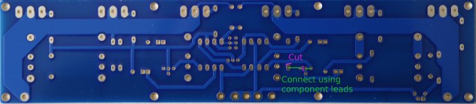
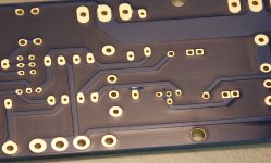
R6 should be connected to the node between P2 and C4 instead of as it is now between P2 and R22. The mistake can be fixed relatively easily by cutting two traces and extending the leg of R22 to connect to the other end of P2 and bending one leg on P2. I have attached a drawing of what needs to be done to fix the problem.
I have already written to those who have ordered, so if you have ordered, but not received the mail, please write to me.
I still have more boards left and I'll cut the traces so that the boards can be used virtually without any extra effort. However since people might not like to have to stretch a leg on a resistor, I'll lower the price from $9 to $7.
Good news is that it is fixable.
R6 should be connected to the node between P2 and C4 instead of as it is now between P2 and R22. The mistake can be fixed relatively easily by cutting two traces and extending the leg of R22 to connect to the other end of P2 and bending one leg on P2. I have attached a drawing of what needs to be done to fix the problem.
I have already written to those who have ordered, so if you have ordered, but not received the mail, please write to me.
I still have more boards left and I'll cut the traces so that the boards can be used virtually without any extra effort. However since people might not like to have to stretch a leg on a resistor, I'll lower the price from $9 to $7.
Attachments
Just as with the F5, I have made a blog post, where I will make a guide for the F4. You can see it here: http://www.diyaudio.com/forums/blogs/cviller/198-my-f4-guide.html
I have used a dremel with a cutting disc on the boards I have shipped after discovering the problem.
Thank's, Eric
cviller
What component for D, R and C do you have in mind for this board.
Sincerely
Eivind Stillingen
You might want to check out this thread: http://www.diyaudio.com/forums/group-buys/142565-gb-rectifier-boards.html
- Status
- This old topic is closed. If you want to reopen this topic, contact a moderator using the "Report Post" button.
- Home
- Group Buys
- Gb: F4 pcb