DVD
Crom just made me aware of the Rohpoint GG102A resistors that you are recommending
Do you have any idea what value would be suitable for BIII as the I/V resistors?
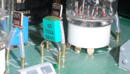
Also in the attached photo's it shows little brass stand offs, do you know what they are called I'm having trouble finding them?
Crom just made me aware of the Rohpoint GG102A resistors that you are recommending
Do you have any idea what value would be suitable for BIII as the I/V resistors?
Also in the attached photo's it shows little brass stand offs, do you know what they are called I'm having trouble finding them?
Attachments
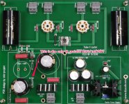
DQ828, Phew, glad you saw that tb1- tb2 connection that was needed -that's what I was trying to point out to you a while back. Make sure it happens on the tube side as per picture.
Re the I/V resistor, I'm using stock 56R and it sounds lovely. Russ / Brian from Twisted pear seem to recommend experimenting from 20R-32R so I've bought a few options which I'll be trying over the next week or so. I'll report back. I think the difference that you should notice is that it distorts (or you lose separation between the instruments) when you play it loud. I think it has something to do with the ability to deal with voltage swings. However, if someone can explain the logic behind the values I'm all ears ;-)
Re the I/V resistor, I'm using stock 56R and it sounds lovely. Russ / Brian from Twisted pear seem to recommend experimenting from 20R-32R so I've bought a few options which I'll be trying over the next week or so. I'll report back. I think the difference that you should notice is that it distorts (or you lose separation between the instruments) when you play it loud. I think it has something to do with the ability to deal with voltage swings. However, if someone can explain the logic behind the values I'm all ears ;-)
DQ828, Phew, glad you saw that tb1- tb2 connection that was needed -that's what I was trying to point out to you a while back. Make sure it happens on the tube side as per picture.
Yes, thank you, I was torn between advice.

I was using 30R and it sounded better than 56R in my tests.
BTW, if anyone wants a Tube-I-Zator, I'm selling mine. I changed my entire DAC so it is available.
Don't get me wrong, it is an absolute amazing I/V but I decided to leave tubes for a while. In all I have built 4 of the Tube-I-Zator!
I had a balanced setup but one is already sold. I'm using ClarityCAP MR on coupling and TX-2575 for R I/V (x2) and Rk (x4). Salas SSHV2 for high tension and the Tubes are TJ Full Music 12AX7. All parts are very good quality.
See here : http://www.diyaudio.com/forums/swap-meet/222479-fs-tube-i-zator-dac-iv.html
See here for my first two boards using DVBProjekt / Salas SSHV1 post #543
http://www.diyaudio.com/forums/group-buys/156149-tube-i-zator-professional-pcb-55.html
Thanks
Do
In the photo of post #741, where can I get the little sockets the resistors are plugged into? They look ideal (as their use in the photo suggests) to swap things and test them without soldering/desoldering. Thanks.
That's what I want to know
Well with the yellow wire in place it makes no difference to the voltage, The SSHV Vin is reading 161V & the Vout is reading 151V DC this is after about 20min with the tubes in place.
I still have one very hot heat sink & one luck warn, if fact it may be picking it's heat up from the heat sink beside it, as you don't need to put you finger on it to know it's hot ouch.
I still have one very hot heat sink & one luck warn, if fact it may be picking it's heat up from the heat sink beside it, as you don't need to put you finger on it to know it's hot ouch.
Well with the yellow wire in place it makes no difference to the voltage, The SSHV Vin is reading 161V & the Vout is reading 151V DC this is after about 20min with the tubes in place.
I still have one very hot heat sink & one luck warn, if fact it may be picking it's heat up from the heat sink beside it, as you don't need to put you finger on it to know it's hot ouch.
The different temperatures on the heatsinks are normal. In our configuration we have a power dissipation of ~5.8W for IRF840 and ~1.2W for IRF9610.
With the usage of R1=56R (current adj.) we get a constant current of ~40mA.
If everything is ok, the SSHV input voltage should be ~180VDC.
I remember that one member had a problem with his transformer, witch wasn´t able to get a stable voltage for 40mA current...
Anyway, how changes your input voltage, when you turn the output voltage slowly down?
Perhaps we must lower the resistor value in the C-R-C filter a bit, to get more input voltage to the SSHV.
And lastly is it normal for the heater elements to glow brightly for about a second when you first turn it on?
The heater flash on startup is normal for a wide family of tubes. Nothing to worry about.
Last edited:
Also in the attached photo's it shows little brass stand offs, do you know what they are called I'm having trouble finding them?
Get normal 2.54mm component straight sockets like the Mill-Max 310...001 series. Get rid of the plastic and you could use the pins as on my photo
Thank you so much, this would have saved a couple of PCB's lives had I used them...Get normal 2.54mm component straight sockets like the Mill-Max 310...001 series. Get rid of the plastic and you could use the pins as on my photo
I remember that one member had a problem with his transformer, witch wasn´t able to get a stable voltage for 40mA current...
Don't say that I spent a fortune at a local manufacturer on the transformer, could has easily upped the amperage at the time
Anyway, when I turn the unit on the voltages are 131out 156in
I then turned it down a bit I got 120out 156in
I do have a 5v 3A secondary on the transformer that is not going to be used can it come into play somehow?
Ive been wondering how I could test the transformer to see if can really supply the 150v 0.1A. If I supplied a resistance of 1540 Ohms & checked the voltage across the resistor, and if it was still 150V then it would be suppling the 0.1A @150V therfore theoretically it wouldn't be the transformer causing the problem. Does that make sense?
How could I safely create 1540 ohms of resistance?
How could I safely create 1540 ohms of resistance?
Last edited:
dvd
"Perhaps we must lower the resistor value in the C-R-C filter a bit, to get more input voltage to the SSHV."
Which resistor should I change & can you recommend what ohm's it should be?
Can it be a 1/4W Metal film?
I assume by not having the correct voltage at the input I have less shunt mA.
What would be the effect to the music signal of lowering the voltage to the tubes to say 140v?
Which resistor should I change & can you recommend what ohm's it should be?
Can it be a 1/4W Metal film?
I assume by not having the correct voltage at the input I have less shunt mA.
You could change the 1K0/2W resistor in the C-R-C to 820R/2W to get more input voltage to the SSHV. The drawn current stays at ~40mA (56R at SSHV).
Best regards,
Oliver
You could change the 1K0/2W resistor in the C-R-C to 820R/2W to get more input voltage to the SSHV. The drawn current stays at ~40mA (56R at SSHV).
Best regards,
Oliver
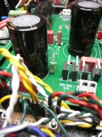
The attached photo shows the 1k resistor I think you are talking about but it is not 2W?
Will a 1/4 Metal film do instead?
Attachments
The attached photo shows the 1k resistor I think you are talking about but it is not 2W?
Will a 1/4 Metal film do instead?
Did you use a 1K0/0.25W resistor? With the SSHV you must use a 2W resistor! (see BOM)
Please measure the resistor value. I think you had blown up the 1K0...

Did you use a 1K0/0.25W resistor? With the SSHV you must use a 2W resistor! (see BOM)
Please measure the resistor value. I think you had blown up the 1K0...
Sorry, I just read what it said on the board, it is a 2W resistor.
I will get a 820R resistor instead
Sorry for the confusion
Attachments
I was using 30R and it sounded better than 56R in my tests.
Hi pinnocchio, can you describe 'better' in a little more detail. i'm fiddling with different values and am having trouble telling the difference. I read elsewhere that it affected the quality at different volumes?
Thanks.
Did you use a 1K0/0.25W resistor? With the SSHV you must use a 2W resistor! (see BOM)
Please measure the resistor value. I think you had blown up the 1K0...
Trying to buy Carbon resistors to meet the requirements (without going to a special OS supplier for 1 resistor) is impossible, can I just use metal film, why the carbon?
- Status
- This old topic is closed. If you want to reopen this topic, contact a moderator using the "Report Post" button.
- Home
- Group Buys
- Tube-I-zator Professional PCB