Oliver:
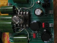
Probably not what you had in mind when you designed board.
As soon as my transformer arrives I will attach this to my Buffalo II.
Enjoy
Bob
I now have this up and running with the Buffalo II. It does use the Buffalo in voltage mode. Everything the Lampizator says in his Buffalo article sure rings true as I am listening.
Best
Bob
Oliver,
How do you adjust the output gain of TubeIzator?
My preamp is keep on giving a clipping signal even though I set the input level to (-12) minimum. I'm using the 12AX7 tube and the parts that is on your parts list with Buf II. Thanks.
Joe
Joe,
if you must adjust the gain level, please change the tubes.
The 12AX7 has a gain of 100.
You could change to the 6N6P (gain=22) with Rk= 250 Ohm for example.
For this you should reduce the B+ voltage to ~120V (adjust the two resistors in the anode supply).
Best,
Oliver
I have been tube rolling, 12ax7 sounded very good, and 6dj8, 12at7, 12au7, not as good. Maybe just because of the different tube brand, but they were all NOS.
And my shipment of 6n1p-ev, 6n2p-ev and 6n6p have arrived, 6n6p sounded the best with the V-out dac, I haven't switched back to the Buffalo yet.
And my shipment of 6n1p-ev, 6n2p-ev and 6n6p have arrived, 6n6p sounded the best with the V-out dac, I haven't switched back to the Buffalo yet.
My idle hands and racing mind do not make a good combination.I was going to sell my Marantz SA-15S1 player, but after getting the service manual, I decided to Lampizat it, and being a voltage out DAC (CS4398), I added a 1uf cap at the input and changed Ri/v to 250k. The result is much better than I expected, now I can listen to all my SACD's with this nice output module. I think my digital source system is complete (for a while at least) with:
1. Squeezebox to Buffalo II to Tube-I-Zator.
2. Marantz SA15 to Tube-I-Zator.
Thanks Oliver!
toufu
I may have missed it but are you using the Buffalo in current mode? Are you just using one of the phases?
I posted my pix of the 6SN7/6H8C setup I put together. It takes both phases (+ and - ) and inputs SE. It sounds great. Right now I am switching between this set-up and my Lundahl 1674 transformers. the transformers also sound very good and make for a nice compact system.
Best
At least the recommended transformer:
R-Core Transformer / ebay seller: diy-goods
R26-90: 0-150V, 0-9V X2
I finally received this transformer. There is one problem though. The 150V reads close to 200v (198). Is it possible to adjust for this (to high) voltage with resistors and if so what resistor values/watt do I need and where do I place them at the board.
Any help is highly appreciated.
Thanks
Oliver:
I forgot to mention that my RCore transformer was putting out 270V so I put some 33K resistors in the anode line. Gives 210V to the 6H2P. Is this OK or should I drop the voltage more.
In general I have found that the RCore transformers run a bit higher than stated.
Best
Bob
Where is the best place to put these resistors?
Thanks
[QUOTE=flocchini;
I posted my pix of the 6SN7/6H8C setup I put together. It takes both phases (+ and - ) and inputs SE. It sounds great. Right now I am switching between this set-up and my Lundahl 1674 transformers. the transformers also sound very good and make for a nice compact system.
Hi Bob,
If you have to pick one which is the better on all of what you've tried so far?
Thanks,
Joe
Where is the best place to put these resistors?
Thanks
I put them in place of the B+ jumpers that appear on the left side middle of the board.
flocchini; I posted my pix of the 6SN7/6H8C setup I put together. It takes both phases (+ and - ) and inputs SE. It sounds great. Right now I am switching between this set-up and my Lundahl 1674 transformers. the transformers also sound very good and make for a nice compact system. Hi Bob said:Joe:
I am using the 6SN7 set-up. Right now it appears a bit fuller with more punch
Enjoy
Bob
that should have read outputs SE
Where is the best place to put these resistors?
Thanks
You could also rise the value of the two 1K resistors in the anode supply
directly.

Joe:
I am using the 6SN7 set-up. Right now it appears a bit fuller with more punch
Enjoy
Bob
that should have read outputs SE
Hi Bob, I might have missed your picture of the 6SN7 setup, can you direct me to it? I might want to try that too... Thanks!
The pix of the 6SN7 is in post 102 (this thread).
I have a bunch of 6SN7 tubes so it was a logical choice. It does use the V+ and V- outs of the Buffalo and gives an SE output. I used Oliver's board for the power supplies and the ground plane and as a base for the Amphenol 8 pin tube "test bench". Hard-wired the circuit to that.
I recently replaced the PIO output caps with Mundorf Silver/Oil and a .1μF Russian Teflon. I think this gave the sound more body and punch.
Best
Bob
I put them in place of the B+ jumpers that appear on the left side middle of the board.
Thanks. Yes, that seems to be a natural place to put them. I tried some 27,5k resistors and that gives me around 210v at the anode.
You could also rise the value of the two 1K resistors in the anode supply
directly.
Thanks. If 27,5k + 1k gives me around 210v then I guess I need a resistor around 33k in this position to get a voltage between 180-200v?
Do you think this way of doing it will be preferable sound vice compared to adding two resistors in the anode line?
Sorry for the noob questions but I'm new to this hobby.
Last edited:
Thanks. If 27,5k + 1k gives me around 210v then I guess I need a resistor around 33k in this position to get a voltage between 180-200v?
Do you think this way of doing it will be preferable sound vice compared to adding two resistors in the anode line?
Sorry for the noob questions but I'm new to this hobby.
If prefer one resistor buy you could also do it with two in series.
- Status
- This old topic is closed. If you want to reopen this topic, contact a moderator using the "Report Post" button.
- Home
- Group Buys
- Tube-I-zator Professional PCB