Hi everyone
I am sourcing parts for the tube-i-zator board and I am not sure which value for the R i/v I should get. I'm using the Buffalo ess9008 as dac, in the manual it says that:
"The output of the buffalo can be used as a voltage source or a current source. Best DNR and THD will
be achieved using it as a current source.
The differential output of the buffalo is 0.924*1.65V (3.1746 Peak) + 1.65 DC bias and the series
output resistance is nominally 195 Ohms at each output."
So I understand that I can configure for either V or I output? But the value will be different for each configuration right? And in either case I dont know how to calculate the R value I should get.
Hi neda,
the russian military 6N2P are balanced between the two triodes inside AFAIK.
That is recommended for every tube in a SRPP circuit like the Tube-I-zator.
To get an optimal channel balance i would prefer also to use a matched pair.
The SSHV shunt should be set to 150V output voltage, yes.

the russian military 6N2P are balanced between the two triodes inside AFAIK.
That is recommended for every tube in a SRPP circuit like the Tube-I-zator.
To get an optimal channel balance i would prefer also to use a matched pair.
The SSHV shunt should be set to 150V output voltage, yes.
Hi Oliver,
Hope you had a great weekend.
The BOM calls for .25w resistors in the anode power supply section of the tube-i-zator, but in your photo it looks like your using 1/2watt's.
Which size do you recommend?
Best,
Ned
Hi Ned,
that depends strongly on your HV PSU Setup. If you use the standard setup with the 6N2P, you have P=U*I :
An externally hosted image should be here but it was not working when we last tested it.
1,2V*1,15mA=1,4mW, so a 0,25W resistor is ok.
If you use the SSHV-Shunt Module set with the 56R to the recommended ~36mA shunt current, you have:
An externally hosted image should be here but it was not working when we last tested it.
38V*38mA=1,44W. So the resistor must be changed to a 2W type.
Last edited:

Oliver,
Are you powering the tube-i-zator, and shunt module with the 120v or 150v tap of your trany?
Ned
Ned,
yes.
The Tube-I-zator stand alone with the 120V tap and with the SSHV Shunt module, i switch to the 150V tap.
Wow Oliver, those receptical pins for the output resistors were tough to solder in straight. I got them done though. Thanks for the link to buy them! I have the Tube-I-zator V2.0 with the Buffalo II Balanced version almost complete now! I just need to solder the analog and digital wires to the XLR and RCA jacks. I will post some pictures when I am done. I appreciate all your help with this Oliver. I may need to ask a few more questions before I am done though. I hope you don't mind.
Greg
Greg
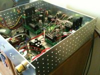
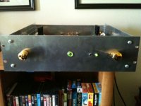
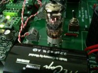
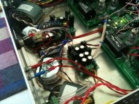
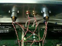
Got some photos of the balanced version of the Tube-I-zator boards with the Twisted Pear Buffalo II DAC. Fully balanced version plus single ended. I have some Telefunken ECC88/6DJ8 tubes in it now. Sounds phenominal!! I would like to thank Oliver for all his help, I could not have done it without him. Thank you Oliver!!! Pictures are below!! Sorry for the bad quality as they are from my Iphone.
Greg
Pictures are below!! Sorry for the bad quality as they are from my Iphone.Greg
Attachments
Last edited:

- Status
- This old topic is closed. If you want to reopen this topic, contact a moderator using the "Report Post" button.
- Home
- Group Buys
- Tube-I-zator Professional PCB