Last night I turned the pot around and cobbled together a heat sink out of an old Pentium 2 heatsink. In this application, overkill is an understatement for that sink. I would rather too much sinking than not enough, and that is what I have. I left things running for a little over an hour last night, and the DC offset was still sitting about 6 mV on the left channel. Tonight my plan is to swap around the matched fets and see if I can get things in to spec. I will post some pictures later.
You can run it with 82R//82R instead. That will get it down to the original 2X12 & single bridge design dissipation (around 44c on bare Mosfets with 33 ambient). 2X15 trafo is good for mains variations all over the world, 2X12 is good for solid 230V/115V areas and saves on dissipation with original 68R//68R. I would prefer to have the 2X15V mains margin benefit and go lower in constant current instead with 82//82R, if in an akward situation. I.e. Varying or under nominal mains, inside a hot tube or class A sand as integrated, smallish box near a radiator, no space around or on top to take sinks, no metal floor near to fast the MOSFETS when soldered underneath PCB, etc.
All right, I am now up and running. I got the DC offset to be less than 3.5mV on both channels by swapping around the jfets. 4th combo and position was the key. Persistence paid off. I let things warm up and run in a bit and then sat down to listen. I have pried myself away after about 2 albums to write this. This thing is incredible. I am listening to a pair of axon home theater speakers (zalytron design) through chip amp and this B1. I have had the speakers up and running for about 2 months and thought them to be OK. A bit veiled, missing detail and definition, but ideal for home theater with plenty of bass kick and treble extension. Well, remove the Harmon Kardon preamp and drop in the B1 and I have to change my initial evaluation of the speakers. Of course that means that the B1/Gainclone combo is a big step up from what I was hearing before. This thing is passing huge amounts of micro dynamics and detail. The top end is just what you feed it and the bass is all there with impact and the mids are all there with all the emotion. I was listening to Marc Cohen's Walking in Memphis and it made the hair on my neck stand up. That hasn't happened with that album in some time.
Dave is a happy boy. I will review the BOM tomorrow, but for now, I have to say that this GB is good to go.


 +
+  =GB=
=GB=
 For the chatter guys an idea. Maybe you try a Darlington instead? A BC517 has same pin order. Only for the one under the coil I mean. I never got the chatter hickup so to have it in my hands and come around fixing for some rebelious relays. Never got such aswell. Difficult ones could succumb under more current gain me thinks.
 But maybe a silly idea. OK I shut up.
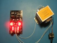
PCB was in the mailbox this afternoon when I got home from work ") Some progress was made as far as filling the board. Tomorrow I may get it hooked up with some music.
Some progress was made as far as filling the board. Tomorrow I may get it hooked up with some music.
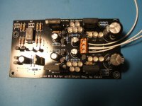
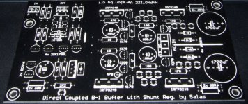
It is obvious that crt has layed out more than a few PCB's in his time, and has his preferences for pad and hole sizes. The quality is good. It is well laid out and this makes it easy to build. I hurried it up a bit so I could get back to you guys who are waiting on the last of the proto builders, so a decision on a go-ahead for PCB production can be made soon. I remember Salas saying something about LED sizes, now I understand, 5mm LED's will not fit flat on the PCB.
No relay chatter, it turns on after about 3 to 4 seconds, the part number of the one I am using is GP-212 and the manufacturer is Goodsky. I am not using an LED in the cct near the timing cct for the relay yet. I put a 100nF cap in the cap position next to the LM7812, i.e. the unmarked cap on the input to the LM7812, and the LM7812 manufacturer is STI. The AC input from the 60VA 15-0-15 tranny is 16.5 and 17.4V, the DC out from the rectifier is 23.8 and 23.6, the regulated DC is -9.74 and +10.04, the DC offsets are -1.1mV and -0.5mV. Hope this info helps. Time to eat and go to bed now...
http://i198.photobucket.com/albums/aa160/birdy81260/Buffer1.jpg
http://i198.photobucket.com/albums/aa160/birdy81260/Buffer2.jpg
Some progress was made as far as filling the board. Tomorrow I may get it hooked up with some music.It is obvious that crt has layed out more than a few PCB's in his time, and has his preferences for pad and hole sizes. The quality is good. It is well laid out and this makes it easy to build. I hurried it up a bit so I could get back to you guys who are waiting on the last of the proto builders, so a decision on a go-ahead for PCB production can be made soon. I remember Salas saying something about LED sizes, now I understand, 5mm LED's will not fit flat on the PCB.
No relay chatter, it turns on after about 3 to 4 seconds, the part number of the one I am using is GP-212 and the manufacturer is Goodsky. I am not using an LED in the cct near the timing cct for the relay yet. I put a 100nF cap in the cap position next to the LM7812, i.e. the unmarked cap on the input to the LM7812, and the LM7812 manufacturer is STI. The AC input from the 60VA 15-0-15 tranny is 16.5 and 17.4V, the DC out from the rectifier is 23.8 and 23.6, the regulated DC is -9.74 and +10.04, the DC offsets are -1.1mV and -0.5mV. Hope this info helps. Time to eat and go to bed now...
http://i198.photobucket.com/albums/aa160/birdy81260/Buffer1.jpg
http://i198.photobucket.com/albums/aa160/birdy81260/Buffer2.jpg
Attachments
Last edited:
Is there any positive feedback from the relay drive to the control signal input?
As the transistor starts to send current through the relay the positive feedback increases the speed of activation and ensures a hard switch on signal without chatter.
Without feedback the signal rises slowly and if the source impedance feeding the relay is high the current falls as the relay starts to pull in and falls open again.
This problem will be alleviated by using lower current, higher voltage relays. 5V need lots of current, 24V need tiny current by comparison.
Good news on the Chattering relay problem - seems the 7812 quality is the reason. I changed the 7812 ( ofcourse my original build had filter 0.1uf Cap as somebody had asked me about it) to JRC brand as the original one was from some unknown make - the chattering is gone - no need for cap
I think Tea Bag also can try changing his 7812 to check this out.
kannan
Is there any positive feedback from the relay drive to the control signal input?
As the transistor starts to send current through the relay the positive feedback increases the speed of activation and ensures a hard switch on signal without chatter.
Without feedback the signal rises slowly and if the source impedance feeding the relay is high the current falls as the relay starts to pull in and falls open again.
This problem will be alleviated by using lower current, higher voltage relays. 5V need lots of current, 24V need tiny current by comparison.
Our solution so far is a 0.15u mylar or ceramic capacitor from collector to base of the relay pulling NPN. That makes it work normally.
PCB was in the mailbox this afternoon when I got home from work
It is obvious that crt has layed out more than a few PCB's in his time, and has his preferences for pad and hole sizes. The quality is good. It is well laid out and this makes it easy to build. I hurried it up a bit so I could get back to you guys who are waiting on the last of the proto builders, so a decision on a go-ahead for PCB production can be made soon. I remember Salas saying something about LED sizes, now I understand, 5mm LED's will not fit flat on the PCB.
No relay chatter, it turns on after about 3 to 4 seconds, the part number of the one I am using is GP-212 and the manufacturer is Goodsky. I am not using an LED in the cct near the timing cct for the relay yet. I put a 100nF cap in the cap position next to the LM7812, i.e. the unmarked cap on the input to the LM7812, and the LM7812 manufacturer is STI. The AC input from the 60VA 15-0-15 tranny is 16.5 and 17.4V, the DC out from the rectifier is 23.8 and 23.6, the regulated DC is -9.74 and +10.04, the DC offsets are -1.1mV and -0.5mV. Hope this info helps. Time to eat and go to bed now...
http://i198.photobucket.com/albums/aa160/birdy81260/Buffer1.jpg
http://i198.photobucket.com/albums/aa160/birdy81260/Buffer2.jpg
Very nice indeed. Your transformer sounds like a 2X17VAC to me, so help the CCS Mosfets with some little sinks.
Attachments
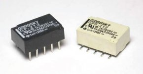
Good news on the Chattering relay problem - seems the 7812 quality is the reason. I changed the 7812 ( ofcourse my original build had filter 0.1uf Cap as somebody had asked me about it) to JRC brand as the original one was from some unknown make - the chattering is gone - no need for cap
I think Tea Bag also can try changing his 7812 to check this out.
kannan
Thanks Kannan, I've added your input to the BOM V3.6.
Same regulator reference L7812ACV from STMicroelectronics, ref for Farnell's modified (L7812CV in V3.5), Mouser's one was right confirmed by BillyK.
Last edited:
Good news on the Chattering relay problem - seems the 7812 quality is the reason. I changed the 7812 ( ofcourse my original build had filter 0.1uf Cap as somebody had asked me about it) to JRC brand as the original one was from some unknown make - the chattering is gone - no need for cap
I think Tea Bag also can try changing his 7812 to check this out.
kannan
I used this one.
512-LM7812CT
I typically buy Fairchild components......
I will order one that works when I get another order to mouser going.
Have we moved from the google spreadsheet to the new wiki system here?
Fran
Fran, I have no intentions of using the new Wiki system for this group buy.
Once the qoute comes back for roughly current quantities, price will be set and then it will quickly move to pay-up time. I want to put the order in for the PCB's on October 12th. So last day to pay will be the 11th. Price will be set hopefully in the next few days.
I want to get this GB moving along. We'll decide about latecomers later on.
Probably another small quantity next year may be warranted, assuming internal selling of extra's occurs first.
++Fran, I have no intentions of using the new Wiki system for this group buy.
Once the qoute comes back for roughly current quantities, price will be set and then it will quickly move to pay-up time. I want to put the order in for the PCB's on October 12th. So last day to pay will be the 11th. Price will be set hopefully in the next few days.
I want to get this GB moving along. We'll decide about latecomers later on.
Probably another small quantity next year may be warranted, assuming internal selling of extra's occurs first.
Fran, I have no intentions of using the new Wiki system for this group buy.
Once the qoute comes back for roughly current quantities, price will be set and then it will quickly move to pay-up time. I want to put the order in for the PCB's on October 12th. So last day to pay will be the 11th. Price will be set hopefully in the next few days.
I want to get this GB moving along. We'll decide about latecomers later on.
Probably another small quantity next year may be warranted, assuming internal selling of extra's occurs first.
Good move - let us get going with this as changing it to wiki will add another confusion among the participants
kannan
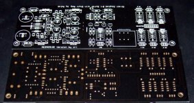
Got the PCBs from Tea-Bag today. The quality is MUCH better than our quick amateur photos can capture. They are like plexiglass in reality. Thick and shiny and take a negative film like dark brown pearl gloss when passing light. Pitch black normally. The silkscreen is sharp and the pads perfect. They remind of an ASUS board. Kudos to Crt and Tea-Bag.
Attachments
- Home
- Group Buys
- GB for DC coupled B1 buffer with shunt PSUs