OUT means positive output, negative is common ground on main filter caps, see more info here: http://www.diyaudio.com/forums/group-buys/140306-f5-pcb-group-buy-23.html#post2218345
Last edited:
Pass DIY Addict
Joined 2000
Paid Member
")
Have you made PSU boards too??
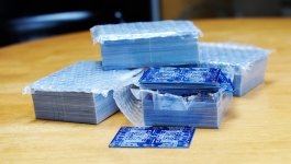
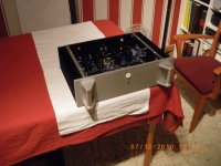
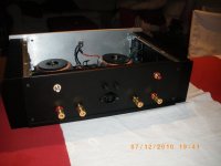
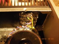
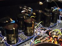
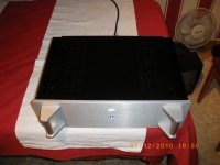
BTW, here's my F5 with Peter Daniel's boards. Great quality and design, nice boards!
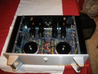
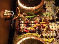
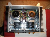
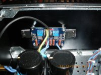
I haven't finally used the thermistor nor the current limiting protection. I have used Caddocks MK132 as the board is intended to, and mills resistors. No input capacitor, DC coupled. These are two mono channels each with its own PSU and trafo. Here I used 250VA each and up to 88.000uF per channel in a CRC configuration.
At the moment I have it biased at 1A per mosfet (not 1.3A as Nelson proposes). Is there any difference if I take it lower? What would be the minimum advisable? In very rare occasions I pull more than 1W per channel, and heatsinks seems to be a bit on the small side.
BTW, here's my F5 with Peter Daniel's boards. Great quality and design, nice boards!
I haven't finally used the thermistor nor the current limiting protection. I have used Caddocks MK132 as the board is intended to, and mills resistors. No input capacitor, DC coupled. These are two mono channels each with its own PSU and trafo. Here I used 250VA each and up to 88.000uF per channel in a CRC configuration.
At the moment I have it biased at 1A per mosfet (not 1.3A as Nelson proposes). Is there any difference if I take it lower? What would be the minimum advisable? In very rare occasions I pull more than 1W per channel, and heatsinks seems to be a bit on the small side.
Attachments
-
 IMGP2236.JPG452.7 KB · Views: 511
 -
 IMGP2238.JPG362.7 KB · Views: 490
 -
 IMGP2241.JPG463.9 KB · Views: 485
 -
 IMGP2249.JPG510.4 KB · Views: 229
 -
 IMGP2247.JPG355.4 KB · Views: 286
 -
 IMGP2242.JPG542.5 KB · Views: 486
 -
 IMGP2254.JPG461.1 KB · Views: 265
 -
 IMGP2256.JPG441.7 KB · Views: 252
 -
 IMGP2258.JPG489 KB · Views: 243
 -
 IMGP2268.JPG371 KB · Views: 237
I should hope not.In very rare occasions I pull more than 1W per channel,
A 27W amplifier should be ticking along producing an average power of less than 1/4W to leave ~ +20dB of overhead for the transient peaks and thus avoid the worst of the clipping that is inevitable when trying to reproduce good music.
The F5 is a ClassA amplifier upto it's ClassA current limit.
It then moves into ClassAB for any current transients that exceed that ClassA limit. It does this seemlessly.
As an experiment, put the F5 out in the snow, bias it up to 1.3A and listen to the speakers in the comfort of your listening room.
Then bring the F5 back into the warmth and bias it to 700mA. Listen again. Does it sound the same or different?
I have read that higher bias sounds better (Nelson sez it), while other says that hotter sounds better than colder. I don't agree with that last one, if we move inside acceptable limits.
We don't have snow around here so the experiment will be difficult to perform. Should I bet higher current in colder conditions achieve better sound, due to transient peaks staying in ClassA?
Regards,
Regi
We don't have snow around here so the experiment will be difficult to perform. Should I bet higher current in colder conditions achieve better sound, due to transient peaks staying in ClassA?
Regards,
Regi
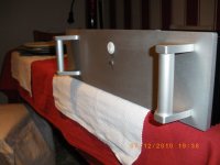
Are you referring to the IEC input or the 'Idontknowhowtosayinenglish' things for holding and screwing wiring terminals?Congrats regi, very impressive work!
One suggestion & one question...
Please, add. wide washer under the mfet screw, even better nice little heatsink...
Were did you find that power-in connectors?
Peter, sorry for OT!
& for fun!
Best regards,
Regi
Are you referring to the IEC input or the 'Idontknowhowtosayinenglish' things for holding and screwing wiring terminals?
Best regards,
Regi
Sorry, it was just a friendly compliment, suggestion and question...
BR,
Have you made PSU boards too??
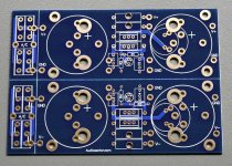
Yes, PS pcbs as described here: http://www.diyaudio.com/forums/audio-sector/149672-universal-power-supply-pcb.html are available as well.
Attachments
Borbely, who also deals exclusively in FET actives, also says that output bias must be >=500mA to get the best out of mosFET output stages.I have read that higher bias sounds better (Nelson sez it), ................ I bet higher current in colder conditions achieve better sound, due to transient peaks staying in ClassA?
As to why it sounds better? Your tentative conclusion could be correct.
Yes, the boards comply with the original circuit schematic, the protection can be fully implemented, if required.
The boards come with a schematic and you can source the parts based on that. There were few BOM files circulating around, but I'm presently away from my computer and don't have access to those, can provide them later though.
The boards come with a schematic and you can source the parts based on that. There were few BOM files circulating around, but I'm presently away from my computer and don't have access to those, can provide them later though.
- Status
- This old topic is closed. If you want to reopen this topic, contact a moderator using the "Report Post" button.
- Home
- Group Buys
- F5 pcb group buy...