Well, let's do some fuse calculations based on a 2x PA150 bridged monoblock setup (500VA - 100.000uF per rail). I am using a softstart board, so they will be fast blow fuses:
For an 8ohm load (Each LM3886 seeing 12ohm, 8x3/2):Having measured a maximum +-30v output swing sine wave, thats 60v over 8ohm, so a total output current of 7.5A. That is 450W (is that right?). Divided across 6x LM3886 IC's, 75W per chip.
For a 4ohm load (Each LM3886 seeing 6ohm):+-30 swing its 60v over 4ohm, so a total output current of 15A. That is 900W.Divided across 6x LM3886 IC's, 150W per chip.
For a 2ohm load (Each LM3886 seeing 3ohm):+-30 swing its 60v over 2ohm, so an output current of 30A. That is 1800W.Divided across 6x LM3886 IC's, 300W per chip.
Hooking a 2ohm load could be a bit over the limit, as LM3886 are specified for 4ohm and here will be seeing 3ohm.
So are those peak currents or constant currents? I may imagine peak, as it cannot really go higher than +-30v.
Should I take worst case condition and make 1800W/220v= 8.18A fast fuse for the primary of the transformer? Or being a design aimed at 300W (BPA-300), should it be 300W/220v= 1.36A fast blow fuse?
I think having heard that LM3886's are limited to 50W per chip, so it shouldn't even be right at +-30v over 8ohm (75W dissipation per chip).
Thank you friends,
Regi
The mains fuse should be related to the transformer, not the amplifiers nor the speakers.
Normally rate the fuse at:-
three times the transformer power divided by the supply voltage.
For close rated fusing, making use of a soft start, aim for:-
transformer power divided by supply voltage. You may find that for either of the above cases that you will need a standard fuse or a slow blow fuse.
If the amp will start reliably with a standard fuse then it is worth trying a fast blow to see how many times it can start up the transformer. You may find that the transformer can start up reliably with an even lower fast fuse value. Once you encounter nuisance blowing then go back up one size.
The secondary fusing is determined completely differently depending on where in the secondary side you place the fuse/s.
If it wasn't clear, 30v is the maximum output before clipping, not the supply voltage. Recalling or not, 30v over 8 ohm is a pretty straightforward calculation, I can't see where those 42v come from....If I recall I dont think you are going to get that kind of wattage at all with only 30V.
Regards,
Regi
Considering the softstart board I am using, it places a power resistor of 100ohm in series with the primaries for the first second after starting it. So at startup, worst case is 2.2A through the primaries.The mains fuse should be related to the transformer, not the amplifiers nor the speakers.
Normally rate the fuse at:-
three times the transformer power divided by the supply voltage.
For close rated fusing, making use of a soft start, aim for:-
transformer power divided by supply voltage. You may find that for either of the above cases that you will need a standard fuse or a slow blow fuse.
If the amp will start reliably with a standard fuse then it is worth trying a fast blow to see how many times it can start up the transformer. You may find that the transformer can start up reliably with an even lower fast fuse value. Once you encounter nuisance blowing then go back up one size.
The secondary fusing is determined completely differently depending on where in the secondary side you place the fuse/s.
Then with a 500VA trafo, and 220v mains, that makes a 2.2A fast fuse. Seems like a nice match.
I will buy some different kind of fuses, with some different ratings above and under 2.2A, and will let them burn (just for the sake of cientific purposes).
Regards,
Regi
BPA-150 success!
One of the simplest amps has given me fits for a couple months. Finally got everything up and running.
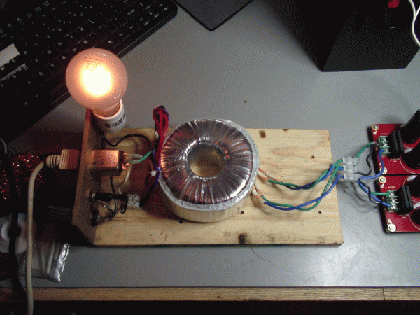
I have to tip my hat to Andrew T who insisted I build and use a dim bulb tester. With the bulb I was able to track the problem down to two non-functioning LM3886 chips. This picture shows the initial surge when the switch is toggled on.

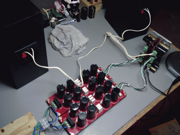
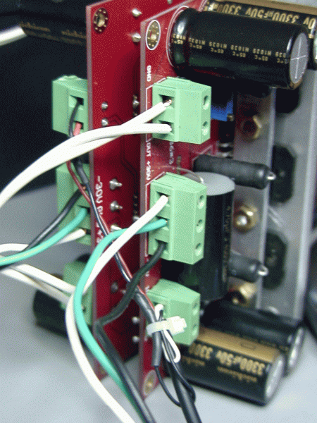
These are the heavy duty power supplies running off one Antek 2224 115V transformer. They both produce 33.4DVC on the money, despite several mini fireworks displays that occurred before I built a second bulb rig to dissipate the PS caps.

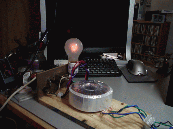
Here is the tester in the process of dimming as the current stabilizes. It goes to full off with higher wattage bulbs and during the process of setting each of the three segments of the BPA150. I found it absolutely necessary to set DC offset to zero one at a time by removing the 0.2R resistors in the other two segments. Not doing so resulted in over voltage that destroyed several caps on the amp board. I never did get one segment lower than 24 on its own, but all three stabilized to 11 after the interactive pot adjustments. That's better than the first board which equalized at 17. I don't know if zero is possible with all three chips active.

Running at full volume from a Sony Walkman CD player the sound is clean, dynamic and with a full and solid tight low end. After running for about an hour, the caps stay at room temp and the small aluminum plate never goes above 101F/38C. I'll use a real heat sink when it goes in the case.

The power supply and amp PCBs were purchased at Jim's audio on ebay. Their customer support during all my good and bad moves was nothing less than first rate.
The components came from both Mouser and DigiKey. This will be the bottom half of my bi-amp project and I'll post again when they are matched up with the MyRefs
Thanks Stanton Tin. And thanks again Andrew for insisting on the dim bulb.
P.S. This was my first shot with surface mount soldering and I'm not afraid any more
One of the simplest amps has given me fits for a couple months. Finally got everything up and running.
I have to tip my hat to Andrew T who insisted I build and use a dim bulb tester. With the bulb I was able to track the problem down to two non-functioning LM3886 chips. This picture shows the initial surge when the switch is toggled on.

These are the heavy duty power supplies running off one Antek 2224 115V transformer. They both produce 33.4DVC on the money, despite several mini fireworks displays that occurred before I built a second bulb rig to dissipate the PS caps.

Here is the tester in the process of dimming as the current stabilizes. It goes to full off with higher wattage bulbs and during the process of setting each of the three segments of the BPA150. I found it absolutely necessary to set DC offset to zero one at a time by removing the 0.2R resistors in the other two segments. Not doing so resulted in over voltage that destroyed several caps on the amp board. I never did get one segment lower than 24 on its own, but all three stabilized to 11 after the interactive pot adjustments. That's better than the first board which equalized at 17. I don't know if zero is possible with all three chips active.

Running at full volume from a Sony Walkman CD player the sound is clean, dynamic and with a full and solid tight low end. After running for about an hour, the caps stay at room temp and the small aluminum plate never goes above 101F/38C. I'll use a real heat sink when it goes in the case.

The power supply and amp PCBs were purchased at Jim's audio on ebay. Their customer support during all my good and bad moves was nothing less than first rate.
The components came from both Mouser and DigiKey. This will be the bottom half of my bi-amp project and I'll post again when they are matched up with the MyRefs
Thanks Stanton Tin. And thanks again Andrew for insisting on the dim bulb.
P.S. This was my first shot with surface mount soldering and I'm not afraid any more
Last edited:
Hey Uriah,
You're reading my mind again. I just hooked them up to a pair of transmission line speakers with high quality drivers (Tang & Band 5" driver and Vifa XT25SC90 1" ring radiator tweeter) that I built last winter.
Without a preamp - feeding the amps direct from the Sony Walkman - I have got to say the sound is excellent. Darn close to the MyRef when listening at the end of a 5' triangle. The placement of all the instruments on a Holst "The Planets" CD is as good as I have gotten from some earphones. Some of the tracks include those bottom organ pipes and they are there, though not what I would call powerful. I am sure the addition of a preamp/buffer will fill in what's missing. The depth of stage is immediately noticeable. On jazz and vocals the BPA150s produce more punch in the mid range and a very solid and responsive low end without any hint of mud.
I am still running with the dim bulb in circuit for a burn-in period before I hook up to the three way Sunflowers for a full comparison. When I take the bulb out I'll have to reset the DC offset as suggested buy Stanton and other builders. At this point I'm guessing the MyRefs will win in the refinement and sparkle comparison, but it's going to be close.
I haven't hooked up the BrianGTs in quite some time but these amps push out a more solid experience than the single LM3886 used on that build. Hopefully I'll have everything in place by tomorrow night and will post again.
P.S. I'm beginning to believe one could combine the LM3886 with rocks, bananas and string and the results would be a good sounding amp.
later...........
You're reading my mind again. I just hooked them up to a pair of transmission line speakers with high quality drivers (Tang & Band 5" driver and Vifa XT25SC90 1" ring radiator tweeter) that I built last winter.
An externally hosted image should be here but it was not working when we last tested it.
Without a preamp - feeding the amps direct from the Sony Walkman - I have got to say the sound is excellent. Darn close to the MyRef when listening at the end of a 5' triangle. The placement of all the instruments on a Holst "The Planets" CD is as good as I have gotten from some earphones. Some of the tracks include those bottom organ pipes and they are there, though not what I would call powerful. I am sure the addition of a preamp/buffer will fill in what's missing. The depth of stage is immediately noticeable. On jazz and vocals the BPA150s produce more punch in the mid range and a very solid and responsive low end without any hint of mud.
I am still running with the dim bulb in circuit for a burn-in period before I hook up to the three way Sunflowers for a full comparison. When I take the bulb out I'll have to reset the DC offset as suggested buy Stanton and other builders. At this point I'm guessing the MyRefs will win in the refinement and sparkle comparison, but it's going to be close.
I haven't hooked up the BrianGTs in quite some time but these amps push out a more solid experience than the single LM3886 used on that build. Hopefully I'll have everything in place by tomorrow night and will post again.
P.S. I'm beginning to believe one could combine the LM3886 with rocks, bananas and string and the results would be a good sounding amp.
later...........
For those who may be interested:
LM3886 x3 150W amplifier PCB Reliable Design ! | eBay
Heavy duty power supply PCB for Pass amplifiers diy ! | eBay
LM3886 x3 150W amplifier PCB Reliable Design ! | eBay
Heavy duty power supply PCB for Pass amplifiers diy ! | eBay
After building several of these fine amps I have decided that 33-34 volts D.C. is a little on the high side for continuous 4 ohm loads. My amps always ran very hot. I finely connected up the BPA 150 units by themselves and ran with less output. This is a very accurate sound. Extremely detailed.
Your build looks very neat and professional. You should get several years of enjoyment out of this construction. DIY is the ONLY way to have quality stereo in your home.
Tad
Your build looks very neat and professional. You should get several years of enjoyment out of this construction. DIY is the ONLY way to have quality stereo in your home.
Tad
Hi Tad, A couple questions if you don't mind. I'm not sure what you mean by "connected up the BPA 150 units by themselves". Are you saying you went from 300 to 150 by separating two PCBs? Also, were you able to get the DC offset all the way to zero and what size transformer did you settle on?
I am very impressed with the sound I'm getting.
Thanks
I am very impressed with the sound I'm getting.
Thanks
Last edited:
I am assembling my BPA-300 to support out-of-the-box using it as an stereo BPA-300 (2x BPA-300) or as 4x PA150 amplifiers (for bi-amping purposes, or running 4 different speakers when needed for party  )
)
I am using a 3 position switch for the inputs (explained for one channel, so half of the amplifier). It switchs input ground too:
-RCA (unbalanced input)-> input balance transformer-> 2x PA150 boards-> speaker between the two output binding posts (BPA-300)
-XLR (balanced input)-> 2x PA150 boards-> speaker between the two output binding posts (BPA-300)
-2x RCA (unbalanced)-> one input for each PA150 board-> one speaker between out and ground, another speaker between the other out and ground. For this purpose, I added a third binding post hooked-up to ground.
I am using a 4-pole switch, the 4th position hooked to a LED to show the position selected (hot, cold, ground, led).
Will upload some pictures of the progress as soon as I can, you'd love 'it. MASSIVE in all aspects.
Last edited:
Have built smd version. I have managed to get an offset as low as 1mvDC and as high as 5 or 6 mvDC, depending of the temperature, it varies. They were calibrated when the IC were warmed up at idle operation. But with an smallish heatsink (those ones from Pentium II, without the attached fan), temperature was 50-60º, what I expect to get playing music with a bigger heatsink.regiregi22,
I have the same question for you. How close to zero Vdc were you able to get after the pot adjustments with all three chips active? Did you build the SMD or the thru-hole version?
What I did was to solder everything EXCEPT the three 0.2ohm output resistors. Then I trimmed each LM3886 with its own trimmer. After playing with offset and readjusting after some minutes, when I was happy with the readings stability, I soldered the output resistors. Final offset won't be 0mvDC, but will be a small value. Then, in the final assembly, I will test them and maybe readjust the pots a little, but the thought work has already been done.
Anyway, when doing the final wiring between the boards, lets say I get those readings from the 4 boards:
-9mvDC
-17mvDC
20mvDC
8mvDC
What I have to do then is bridge board 1st with 4th, and board 2nd with 3rd. This way I will end up with -1mvDC and 3mvDC respectively seen at the speaker terminals. By having 4 boards with 3 trimmers each own, you are able to play quite a little to achieve 0mvDC, don't you think so?
Will tell ya when finally closing it
bcmbob,
The original Jeff Rowland designed BPA300 which Alexw so kindly layout out and supplied the gerber files for us was a bridge parallel amp. Alex first used an opamp to separate and drive the the two signals. He has since incorporated a transformer to split the incoming signal.
Anyway, the bpa300 is two to the bpa150 boards together, one driving the plus input signal the other the minus. You should get close to 300 watts into 4 ohms with the two boards and 150 watts with the single board. The single board will not have the input signal split it will just be plus and ground. I could not tell any audible change in sound quality either way.
I do know that the 150 was much simpler and easier to layout. I am driving a rather unconventional load and have since gone to a discrete Leach type layout. It handles down to 2 ohms with know overheat issues.
The current job on the workbench is my 160 Gu-50 tube amp courtesy of a nice gentlemen on the German web -- Christl Ludwig. He has done all of the hard brain work, including transfromer winding data and such.
Accuracy wise the Jeff Rowland clone BPA300 is right on.
Tad
The LM3886 handles loads down to 4ohms, this question go for the experts: May we assume then that 3 of them in parallel will handle 1.33ohms as a minimum? If so, for how long can you scale it? what load will suppor a 6 or even 12 IC in parallel?I am driving a rather unconventional load and have since gone to a discrete Leach type layout. It handles down to 2 ohms with know overheat issues.
Regards,
Regi
regiregi22 and ted - thanks for your responses. It sounds like the techniques are all very similar. I didn't try adjusting the pots with no resistor - I did each leg with its associated 0,2R in place. I'll give that method a try.
Are you guys using attenuator or preamp/buffer for volume control?
Are you guys using attenuator or preamp/buffer for volume control?
I use that DAC direct to the F5, DC coupled. That DAC outputs no DC current. It has its own volume control:
EMU 0404 USB - really the best?
EMU 0404 USB - really the best?
- Status
- This old topic is closed. If you want to reopen this topic, contact a moderator using the "Report Post" button.
- Home
- Group Buys
- BPA300 Round 2