AndrewT said:the DRV is reputed to not sound the best for audio.
Could someone suggest a good audio line driver?
LM4562, LME48720, THS4131 ...
http://www.shine7.com/audio/bpre.htm
juluska,
you already have the DRV at hand. I don't think you will cause any damage if you try it with the pot. if it sounds right to your ears let it be.
if you insist on building an adapter following ESP you may choose P87B further down the page since it has less parts than your proposal above and has the same ability to present a stable input impedance. to my best understanding all you have to do is to replace the input 22k resistor with a potentiometer with similar value and connect R101 to its variable tap.
I might even try that myself AFTER the SMD parts will get to P-A and he is able to send everything to me.
I hope Rhys keep the momentum he accumulated and is able to deliver another package.
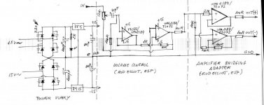
why attenuate and add 10times gain (+20dB) after the buffer followed by the two times gain (+6dB) in the balanced converter and then ~+26dB gain of the power amp?juluska said:another option from me (without any electronics knowledge)
Is it possible to build this in a protoboard with psu and two dual opamps per channel? They are project 1 and project 14 from ESP audio.
That's a total gain of +52dB (~400times). This is bonkers for a conventional source with a peak output of 200mVac to 2Vac.
I send mailperanders said:Could everyone with claims send à message to me please? The persons I am going to send stuff are on the wiki list. I will conducting Rhys' business forever.
shmulik said:juluska,
you already have the DRV at hand. I don't think you will cause any damage if you try it with the pot. if it sounds right to your ears let it be.
if you insist on building an adapter following ESP you may choose P87B further down the page since it has less parts than your proposal above and has the same ability to present a stable input impedance. to my best understanding all you have to do is to replace the input 22k resistor with a potentiometer with similar value and connect R101 to its variable tap.
I might even try that myself AFTER the SMD parts will get to P-A and he is able to send everything to me.
I hope Rhys keep the momentum he accumulated and is able to deliver another package.
Like this?
")
Attachments
Trying things and learning is what DIY is all about, but if you ignore AndrewT's comments you will simply end up being frustrated. Sometimes its nice to try things and have them work well in your particular system. What you are planning will work... in the right system. What Andrew is telling you is that you will have high volume with the volume knob at zero.
Uriah
Uriah
udailey said:Trying things and learning is what DIY is all about, but if you ignore AndrewT's comments you will simply end up being frustrated. Sometimes its nice to try things and have them work well in your particular system. What you are planning will work... in the right system. What Andrew is telling you is that you will have high volume with the volume knob at zero.
Uriah
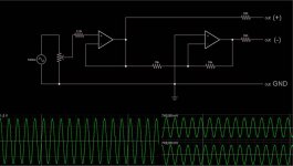
"What Andrew is telling you is that you will have high volume with the volume knob at zero."
Why? See the photo. I will use a 50k pot in the input.
Attachments

Hi,
that new schematic is better.
You can improve it by adding filters at the input to attenuate RF interference and to block DC and attenuate ultra low frequencies from the source/s.
Look at the schematic. the gain of the first amp is 1times (+0dB) that gives 1.5Vac at the input and 1.5Vac at the +output.
The second amp takes the 1.5Vac input and inverts it to give 1.5Vac at the -output.
The difference between the two balanced outputs is 3Vac. A total gain of 2times (+6dB).
Look also at the resistances seen by the input pins of the two opamps.
The first amp sees zero ohms on the -IN pin.
The +IN pin sees a variable resistance from 2k2 to 27k7
This imbalance will create a small output offset from opamp1.
The righthand amp sees 5k on the -IN pin
The +IN pin sees zero ohms.
This will create a small output offset from opamp2.
Your amplifier must block or neutralise these output offsets.
AndrewT said:Hi,
that new schematic is better.
You can improve it by adding filters at the input to attenuate RF interference and to block DC and attenuate ultra low frequencies from the source/s.
Look at the schematic. the gain of the first amp is 1times (+0dB) that gives 1.5Vac at the input and 1.5Vac at the +output.
The second amp takes the 1.5Vac input and inverts it to give 1.5Vac at the -output.
The difference between the two balanced outputs is 3Vac. A total gain of 2times (+6dB).
Look also at the resistances seen by the input pins of the two opamps.
The first amp sees zero ohms on the -IN pin.
The +IN pin sees a variable resistance from 2k2 to 27k7
This imbalance will create a small output offset from opamp1.
The righthand amp sees 5k on the -IN pin
The +IN pin sees zero ohms.
This will create a small output offset from opamp2.
Your amplifier must block or neutralise these output offsets.
I use the 10uf input caps in the pa150 boards, this will neutralise dc offset.
Sorry for my ignorance. You say it will be better using filters at the input of this schematic, another cap perhaps?which value?
Hi,
the cap value depends on your source impedance.
For a pre-amp I suggest you widen the passband by about an octave at each end.
If the power amp does F-1dB from 4Hz to 80kHz then the pre-amp should aim for F-1dB from 2Hz to 160kHz.
We cannot tell you everything about your system. At some stage you are going to have to learn how to measure output impedance and how to calculate your filter component values.
We can guess, you can do a lot better than guessing if you put the effort in.
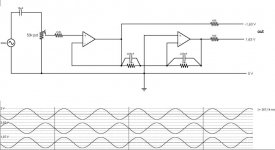
I go for this schematic. I'm now drawing the layout of the protoboard with one only quadruple opamp (TLE2074) for stereo configuration and SMD resistors 0,1% tolerance. The board will measure 40x40mm.
The 10uf input capacitor and the potentiometer will be out of the board.
The input capacitor will be this:
http://wduk.worldomain.net/acatalog/SONIQS_PXX_range.pdf
With this is not necesary a preamplifier.
The 10uf input capacitor and the potentiometer will be out of the board.
The input capacitor will be this:
http://wduk.worldomain.net/acatalog/SONIQS_PXX_range.pdf
With this is not necesary a preamplifier.
Attachments
I'm back!
Hi, guys!
I'm back from the vacation and I'm going to answer and process 20 emails. I really hope that we now have all Rhys' customers now. Some how I feel that I must draw a line somewhere which should be now.
I'll hope most people should have got there stuff from my last shipment.
Hi, guys!
I'm back from the vacation and I'm going to answer and process 20 emails. I really hope that we now have all Rhys' customers now. Some how I feel that I must draw a line somewhere which should be now.
I'll hope most people should have got there stuff from my last shipment.
- Status
- This old topic is closed. If you want to reopen this topic, contact a moderator using the "Report Post" button.
- Home
- Group Buys
- BPA300 Round 2