juluska,
looking at the picture attached to post 878 it seems like you take the speaker lead from ground at the left pa150. compare to alexw pictures.
also, it is hard to see if the shield of the coaxial cable is connected at both ends (drv->pa150). I think the pa150 and the drv must have the same ground otherwise the signal floats.
does that hiss occur also with no input? is it sensitive to placing the whole thing under a metallic cover (or just moving your palms over it)?
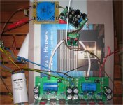
further on the grounding.
pic 878 shows the zero volt return line passing directly over the unscreened termination to the power amp input.
This zero volts line carries pulses and high current audio signals back to the main star ground.
Twist the PSU output triplet so that the field created by the three wires cancels.
Do similar for the power lines into and out of the voltage regulator.
What are the two wires that head off screen to the right?
shmulik said:juluska,
looking at the picture attached to post 878 it seems like you take the speaker lead from ground at the left pa150. compare to alexw pictures.
also, it is hard to see if the shield of the coaxial cable is connected at both ends (drv->pa150). I think the pa150 and the drv must have the same ground otherwise the signal floats.
does that hiss occur also with no input? is it sensitive to placing the whole thing under a metallic cover (or just moving your palms over it)?
Ups!, my mistake connecting speaker terminals. Thanks. Now 90% of hiss has dissapeared. The power is much more bigger. I think i can go for the enclosure and test the complete system and then eliminate any trace of noise.
What about the potentiometer? What is better, 50k or 100k for a passive preamplifier?
Thanks
AndrewT said:for a passive pre a low resistance pot is preferable.
Try 5k or 10k if your source can drive these and the cables adequately.
5k or 10k are ok for drv134?
AndrewT said:where is the drv?
Is it driving the interconnects and the passive pot?
drv134 boards are between passive pot and PA150 boards, see the photo
Attachments
you should consult someone who really understand these things, but if you look in the data sheets of the drv134 you will notice a 10KOhms input impedance. this means that when connecting a potentiometer at the input (taking from the variable tap to the drv input) the source will not see the same impedance in different volume settings. I think the actual impedance would be between 5K (at full volume) to 10K (complete silence) and somewhat non linear behavior even if the potentiometer is linear. the common practice is to use a potentiometer in front of an operational amplifier (input impedance of 1e13 Ohms which is completely swamped by the potentiometer's resistance) or using some other type of active buffering.
this "build it for my sister" thing annoys me to. it starts with a "no problem, very easy, no bother!" and ends as a lifetime project you don't know how to gracefully end...
this "build it for my sister" thing annoys me to. it starts with a "no problem, very easy, no bother!" and ends as a lifetime project you don't know how to gracefully end...
shmulik said:---
this "build it for my sister" thing annoys me to. it starts with a "no problem, very easy, no bother!" and ends as a lifetime project you don't know how to gracefully end...
Oh boy, we have been there...

Arne K

shmulik said:you should consult someone who really understand these things, but if you look in the data sheets of the drv134 you will notice a 10KOhms input impedance. this means that when connecting a potentiometer at the input (taking from the variable tap to the drv input) the source will not see the same impedance in different volume settings. I think the actual impedance would be between 5K (at full volume) to 10K (complete silence) and somewhat non linear behavior even if the potentiometer is linear. the common practice is to use a potentiometer in front of an operational amplifier (input impedance of 1e13 Ohms which is completely swamped by the potentiometer's resistance) or using some other type of active buffering.
this "build it for my sister" thing annoys me to. it starts with a "no problem, very easy, no bother!" and ends as a lifetime project you don't know how to gracefully end...
My sister knows it's difficult for me to build this amplifier because i'm just learning. I'm an architect and i'm about to get back to university to begin my electronics engineering studies while i'm working. It doesn't matter the duration of the project, the finality is learn in the path.
@juluska: if you want to keep it very simple, you can use a simple pot as a passive preamp, but it has to be logarithmic...
but, as stated in the DRV134's datasheet, TI recommends using an active preamp, that is a simple opamp (but something of good quality, like the OPA2104 for better sound, minimum noise).
a very interesting active preamp with tone control is found here: http://sound.westhost.com/project97.htm
You could use just the figure 4 circuit (also, lose the capacitors on the right because you already have an input capacitor on the PA150 boards)
Hi,
if the DRV is between the passive pot and the amplifier then the DRV is not driving the pot.
The DRV is driving the power amp and whatever impedance/resistance you have built into the power amp's input.
What is before the pot?
Can that source/s drive a 5k or 10k passive pot?
if the DRV is between the passive pot and the amplifier then the DRV is not driving the pot.
The DRV is driving the power amp and whatever impedance/resistance you have built into the power amp's input.
What is before the pot?
Can that source/s drive a 5k or 10k passive pot?
AndrewT said:Hi,
if the DRV is between the passive pot and the amplifier then the DRV is not driving the pot.
The DRV is driving the power amp and whatever impedance/resistance you have built into the power amp's input.
What is before the pot?
Can that source/s drive a 5k or 10k passive pot?
A switch, cd player, radio... I don't know if these sources can drive a 10k pot. How can i know it?
rhysh said:Update: The rest of the parts will be going to Per-Anders early next week, using DHL again. This should hopefully not cause a delay as PA has stated he will be away.
And again, a huge thanks to Per-Anders for helping me out
Any updates on this Rhys?
WHAT ABOUT USING THIS PROJECT FOR BRIDGING THE PA150 PCBS?
IS A BETTER SOLUTION THAN DRV134 OR THAT 1646?
http://sound.westhost.com/project14.htm
IS A BETTER SOLUTION THAN DRV134 OR THAT 1646?
http://sound.westhost.com/project14.htm
- Status
- This old topic is closed. If you want to reopen this topic, contact a moderator using the "Report Post" button.
- Home
- Group Buys
- BPA300 Round 2