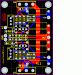
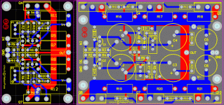
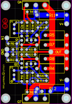
Peter Daniel said:I was playing with the idea of F5 as well, after all it would be nice continuation of the whole series of those mini amp boards.
Peter, could you accomodate the assymetrical mounting pattern (i.e. for the stand offs) that the F4 board uses as well?
oops, just saw your post... yeah, that won't work...
edit: what about accommodating the Caddock power resistors?
Payment sent for one F3 amplifier PCB and one F3 power supply PCB. I will hold off on the F4 boards in favor of the F5 boards that Peter is proposing.
Peter, thank you very much for your service provided.
Mithomas, thank you very much for organizing the Group Buy.
Mr. Pass, thank you very much for sharing your IP.
Peter, thank you very much for your service provided.
Mithomas, thank you very much for organizing the Group Buy.
Mr. Pass, thank you very much for sharing your IP.
Re: F5 board grounds
Does this help?
Input - green is after diode DC 0v, yellow is 18v.
DC input after diodes
white is v+, wire two hear for a channel each. the bare wire is the star ground point, yellow is v-.
V+ V- and ground as bus wire
jims said:Hi Peter
For the F5 board, could not find out grnd, or PS V+ or V- grounds. Are you planning on using a chassis star gnd?
JimS
Does this help?
Input - green is after diode DC 0v, yellow is 18v.
DC input after diodes
white is v+, wire two hear for a channel each. the bare wire is the star ground point, yellow is v-.
V+ V- and ground as bus wire
oups copy cut mistaketristania79 said:Payment sent for 4 x F4 PS, 2 x F3 amp board
I sent payment for 4 x f4 ps and 2 x f4 amp board
- Status
- This old topic is closed. If you want to reopen this topic, contact a moderator using the "Report Post" button.
- Home
- Group Buys
- F3 and F4 Clone PCB Reissue group buy, also F5 PCBs


