Weeeeeeee Confetttttiiiiiii For All!!!!!!
YAAAAA got mine too


 again, you guys are the sh!t! We each owe Uriah and Peter a beer or 12
I love all the notes on the PCB...Russ' doing I assume? Any reason not to socket the LM318? Could someone explain the 2 ground planes? And why one of the big 'lytics + side is tied to the same place as the - of the other big 'lytic? I know I should read the original thread, but it's SOOOOO long. Anyone know where to find a semi-detailed circuit explanation (in english) without having to read all 120+ pages?
And you guys really outdid yourselves with the printed tape part labels & heat sealed packaging ...did you already have equipment to do that?
YAAAAA got mine too
again, you guys are the sh!t! We each owe Uriah and Peter a beer or 12 I love all the notes on the PCB...Russ' doing I assume? Any reason not to socket the LM318? Could someone explain the 2 ground planes? And why one of the big 'lytics + side is tied to the same place as the - of the other big 'lytic? I know I should read the original thread, but it's SOOOOO long. Anyone know where to find a semi-detailed circuit explanation (in english) without having to read all 120+ pages?
And you guys really outdid yourselves with the printed tape part labels & heat sealed packaging
...did you already have equipment to do that?Pink,
As another guy posted we should move these type questions to the SOOOOOO long thread.
The board is all Russ' doing. The lytics tie +and- to make a ground because, technically, you dont earth this board. You just take the secondaries and tie them together in the middle which cancels out their voltage on those ends making 0V and then that 0V plugs in where the +and- of the lytics are. The 'second' ground is connected to the first with a 1R resistor making is still kinda ground but I suppose that keeps the signals from wanting to mix with the noise from the power ground. Make sense?
I personally have one channel that works perfectly and one that doesnt. Perfectly is a kit channel and not perfectly is the prototype. Scary huh? Anyway the prototype probably has a problem cuz there is no soldermask. I have to actually ground it to earth to get it to stop humming and it has issues with capacitance on my speaker wires. The other one, the kit one, has no problems.
Go ahead and socket it. No reason why not. I mean what if you zap your opamp some day with some ESD? Might be nice to have that socket.
Uriah
Pink-
"Any reason not to socket the LM318? "
Because the circuit was designed for the 318 and sockets are usually intended for trying other pin compatible opamps or in "risky" circuits.
Mauro's schematic and Russ' PCB are ROCK solid and if the PCB is assembled correctly the chip will last a LONG time and not give you ANY issues.
So I didn't want to add the extra potential points of failure.
It wouldn't hurt, but there is no reason to.
Nylon bushing: how to drill your holes
For those preparing heatsinks it may be good to know that exact sizing of the nylon bushing for the insulation on the chip. It is part 3102 in this table: http://www.keyelco.com/pdfs/M55p122.pdf
Note in particular that the nylon neck is longer than the chip is thick, i.e., it sticks out and some of it needs to be sunk into the heatsink.
Peter
color coded BOM
Attached is the BOM color coded according to the bags. Yellow is the capacitor bag (everything small is labeled EXCEPT for the 12 220nF bypass caps [small yellow boxes] which correspond to C7/17/18/19/20/21). Blue is for the resistor bag (everything labeled except for the big cement 0R47). The "silicon" bag is highlighted in pink here. Note that the nylon bushings are in that bag loose. So when you open the bag, be sure not to have those little buggers roll off under the couch...
Peter
Attachments
troystg said:
Didn't he do an OUTSTANDING job at packing them!?!?!?
Is he still stuffing them with confetti?

Yes it was packed extremely well, and the confetti did its job!
Got my package yesterday, everything seems in order. Great job thanks Peter and Uriah!
Wish I could say I was going to build this weekend but unfortunately my bathroom floor is giving way, apparently the shower has been leaking for years and years and rotted the joist so I am afraid the commode will end up in the basement, prolly with me sitting on it.
Oh what fun, I just love old houses.
troystg said:Anyone in the US put one together yet?
My boards are stuffed, I have my transformers, enclosure and jacks, just waiting on my heatsinks to arrive!
Coreyk78 said:
My boards are stuffed, I have my transformers, enclosure and jacks, just waiting on my heatsinks to arrive!
Pictures when available please...
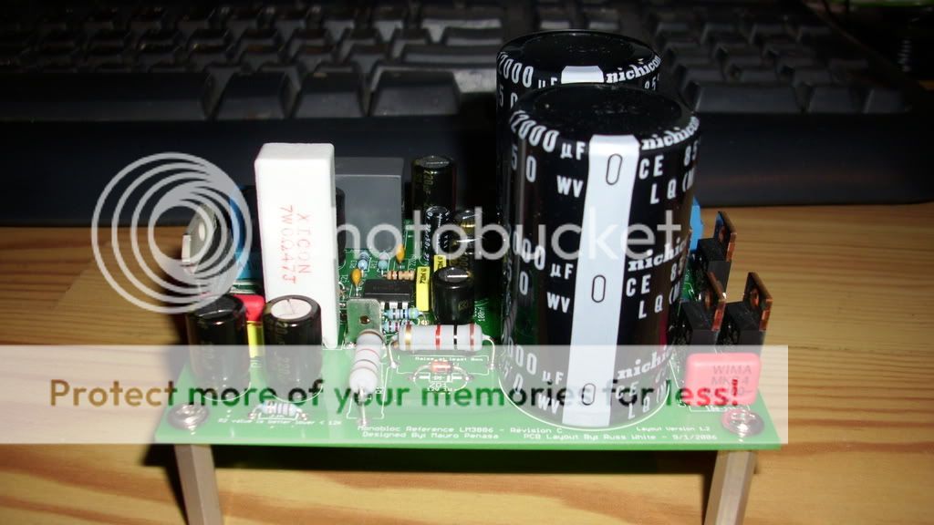
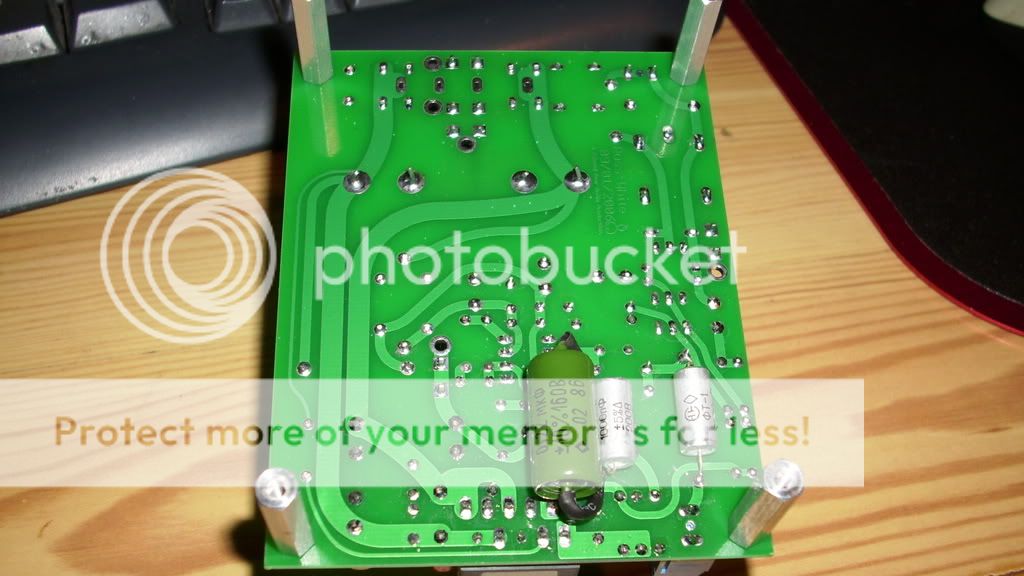
Heres a couple of quickie pictures of one of my boards, I used some Wima .1uf caps for C4 and C5 that I had laying around collecting dust since they fit the lead spacing without having to bend the leads out. I bypassed C13 with a 1000pf FT-1 russian teflon cap, and installed a .22uf rusian pio cap and 1000pf FT-1 in C21. I also used MUR860 rectifiers.
udailey said:
Have fun getting the chip screwed on to a heatsink.
Haha, yeah that may be a challenge, phillips bit in a 1/4" ratchet should be able to get it though.

- Status
- This old topic is closed. If you want to reopen this topic, contact a moderator using the "Report Post" button.
- Home
- Group Buys
- my_ref revC group buy (Mauro Penasa LM3886 design)