Some have shown interest in a group buy for a PSU board in the LYNX Amp PCB group buy here:
http://www.diyaudio.com/forums/showthread.php?s=&postid=1422898#post1422898
Thanks to Carl for taking care of that thread")
Those who are interested can participate here.
I will make the layout and have the PCB's made according to what's decided here in this thread.
The PSU Board should be universal and fitt all common diy Power Amps.
Please come with your suggestions.....
1. What type of rectifier diodes?
2. Should power caps be on the PCB?
If so, what type and how many uF?
3. Connections?
Let the ideas flow
http://www.diyaudio.com/forums/showthread.php?s=&postid=1422898#post1422898
Thanks to Carl for taking care of that thread
Those who are interested can participate here.
I will make the layout and have the PCB's made according to what's decided here in this thread.
The PSU Board should be universal and fitt all common diy Power Amps.
Please come with your suggestions.....
1. What type of rectifier diodes?
2. Should power caps be on the PCB?
If so, what type and how many uF?
3. Connections?
Let the ideas flow
ACD said:Some have shown interest in a group buy for a PSU board in the LYNX Amp PCB group buy here:
http://www.diyaudio.com/forums/showthread.php?s=&postid=1422898#post1422898
Thanks to Carl for taking care of that thread
Those who are interested can participate here.
I will make the layout and have the PCB's made according to what's decided here in this thread.
The PSU Board should be universal and fitt all common diy Power Amps.
Please come with your suggestions.....
1. What type of rectifier diodes?
2. Should power caps be on the PCB?
If so, what type and how many uF?
3. Connections?
Let the ideas flow
Ok, here is some suggestions:
1: TO220 single diodes with room for SK104 heatsinks.
2: Yes, please. At least room for 4 pcs 10mm snapins. Minimum Dia 35mm.
Preferrably, room for 6 pcs, and a filmbypass would also be nice.
3: Pads to make a CRC supply, say provision for 5 pcs 3 watters per rail (Can be jumpered if not wanted). Maybe a bleeder resistor would be nice also, say one 3 watter 3,3K resistor.
It would also be nice to have 2mm connections for making a CLC supply.
5mm spacing for all AC/DC connections for terminalblocks.
Number of GND connections in the DC end: 4. 4 would add great flexibilty if you would use one supply for 2 channels and wanted easy connection of the speaker GND's.
Steenoe,
Why not the three terminal rectifier diodes like the MUR3020/3060? I think those would be a good idea also.
The rest of it sounds good. Maybe a snap off portion to use as a regulator section for the front end of the amp? That would make it truely universal and maybe help sell more of them.
Thanks,
Donovan
Hi Jan
Thanks for the post. I agree with all of the above and would like to include the following.
1. Resistor and LED on board for each rail is a nice touch.
2. Connection points for AC and DC should be screwdriver terminals - the nice heavy three way types are good or faston terminals.
3. I would allow at least 4 off 35mm Diameter snap in caps per rail which would allow over 100,000uF per rail for class A amps.
4 Provision on the board for CRC or CLC. Pads on board for at least 4 resistors (3 watt) in each rail and then provision for terminals for off board air core inductors.
5. Pads for at least 10 watt bleeder resistor to ground for each rail.
6. Provision for film bypass caps for the large electro caps.
7. Diodes mentioned above are both good, but also with provision on board for parallel caps on each diode for suppression.
8. Fully loaded board with large caps will be heavy,so tracks should be as wide as possible for the rails and the board should be made from thicker fibreglass than normal.
These are my thoughts for now.
Regards
Gary..
I see that I forgot to write in the first post, that this is only an interest check, and there are no obligation before layout and price are known
Thanks to all. I find many of your ideas very good but please keep in mind, that this PCB will be large if all ideas are incoorporated......
There are no problem having this made in thicker boards with thicker copper. Price will just be higher!
steenoe and Gary S;
Please specify needed area per Rail for CRC, pad hole size etc.
Jan,
I don't think the larger size and a little more cost will be a problem, as long as this board solves some of the deficiencies of some of the other PS PCB's available.
I for one would be interested in 6-10 of them, as long as they had all of the features that have been brought up.
I think the needed area per rail for the resistors of the CRC section should be enough for 4-5 three watters per rail. I believe that would suit most peoples needs. In the space between them there might be room to fit a bleeder resistor for each rail. That way there shouldn't be any wasted board space.
An idea for the layout could be something like CLCCRC, with 2mm connections for the inductor. Maybe include a linked set of pads for a jumper, or some could use multiple resistors in that area for CRCCRC.
On the capacitor mounts, we could use the standard 10mm snapin mount designed for 35mm, but with just enough room for 40mm diameter caps and linked 7.5 or 5mm pads for underboard bypass caps to save space if needed.
Thanks,
Donovan
Hi Jan
I agree with Landoctor's thoughts. As you mention you want to do this board as a universal PSU board, and a lot of people on this forum are leaning toward class A amps, then a lot of room will need to be allowed for a lot of capacitance for snap in caps.
For people building class AB amps, then they do not have to load all capacitor positions. Amps of this size need plenty of chassis space, which is usually dictated by the size of heatsinking required (especially for pure class A designs), then the PSU board size will be not normally a problem.
Regards
Gary..
CRC/CLCCRC etc.
Most simple way would be to make an area only of pads in two or three different sizes, so people can make what kind of CRC/CLC they wants........
Decoupling/bypass caps
There will be pads for decoupling caps across each rectifier diode, and across all big PSU caps (size LxW: 7.5x4.5mm/pad distance 5mm)
PSU Caps
This will be space for 40mm diameter caps (snap-in) with 10, 7.5 and 5 mm pad distance.
Jan, why don't you have the ground at the left from the transformers? You may assume two separate windings or a centertap transformer.
Place the diodes so you can mount them directly at the mounting plate.
http://groundsound.com/psu12sa.html check out the diode bridge. I have seen an another board with TO247 diodes, can't remember where.
Place the diodes so you can mount them directly at the mounting plate.
http://groundsound.com/psu12sa.html check out the diode bridge. I have seen an another board with TO247 diodes, can't remember where.

Hi Jan
Thanks for posting an initial circuit. My thoughts are as follows:
1. The ground bus should also have pads or terminal block at left of PCB near the AC secondary connection to allow for the 1 or 2 wires from the transformer secondary centre tap winding.
2. You mention the diodes as being TO220 devices - try and incorporate pads for larger TO247/TO3P plastic pack devices as well.
3. The pads for the resistors or inductors for CLC or CRC should be between capacitors C15/C9 and C16/C10. Or you can take it 1 step further and have a second set of pads for CRCRC or CLCLC or CLCRC combinations.
4. Bleeder resistors and indication LEDS should be at DC output.
5. Tracks on PCB for +VDC, GND and -VDC should be as large as possible.
6. For main electrolytic bypass caps C13,C14,C15,C16,C17,C18,C19 and C20 allow for multi pads so people can use their favourite type of film caps - don't just allow 5mm pads.
These are my thoughts so far. Keep up the good work.
Best Regards
Gary..
With all those great ideas comming in, this could easily turn out to be a great design.
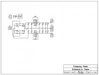
The best place for the "playground" is in the middle of the 'lytic bank. Here is a quick and dirty schematic of what I had in mind initially. Filmbypass caps after the last electrolytic only, is good enough. You can make room for dual diodes also, if you like. Its just a little more complicated to lay out the board. In any case, each rectifierdiode needs its own heatsink, which is best isolated from the rest of the circuit.
The parts in upper left is for LED indication and the 2 parts in the box, is optional if you would like the LED to have its own supply. I didnt bother to connect them.
The R's in the CRC configuration are standard 3 watters with a little extra room. I didnt measure the needed space, but I will do that when I get home. The inductor solder pads need to be with 2mm hole dia at least.
The powertracks should be as big as possible, meaning more or less to fill the board with Cu
Here is another suggestion that will add even more flexibilty. Wouldnt it be nice with a simple LM317/337 supply on the board also?
It would be handy for use with active crossovers and subwoofer controllers amongst other things.
Attachments
- Status
- This old topic is closed. If you want to reopen this topic, contact a moderator using the "Report Post" button.
- Home
- Group Buys
- Power Amp PSU Board (for e.g. LYNX Amp)