Re: Question about 2sc5200/2sa1943
Each transistor needs to be electrically isolated from the heatsink - that's the job of the pads. If well isolated it is not a problem to put one or more channels on a heatsink, because the heatsink is at chassis ground.
But since heat must be conducted away from the transistor you also need low thermal resistance - that the reason for using thermal compounds. Sanding and polishing the contact surfaces is recommended by some -- helps lower the thermal resistance. Thermal compounds are not insulating and must be used in a very thin film, it only fills microscopic uneveness in the mating surfaces.
Before using arctic silver as thermal compound check its properties - I think it is electrically conductive. You don't want to use a conductive material here.
Hope this helps,
Francois
salesmonster said:Newbie question:
Do the heatsinks for each channel need to be electrically isolated from each other? Or can 2 boards share one long heatsink?
Dave
Each transistor needs to be electrically isolated from the heatsink - that's the job of the pads. If well isolated it is not a problem to put one or more channels on a heatsink, because the heatsink is at chassis ground.
But since heat must be conducted away from the transistor you also need low thermal resistance - that the reason for using thermal compounds. Sanding and polishing the contact surfaces is recommended by some -- helps lower the thermal resistance. Thermal compounds are not insulating and must be used in a very thin film, it only fills microscopic uneveness in the mating surfaces.
Before using arctic silver as thermal compound check its properties - I think it is electrically conductive. You don't want to use a conductive material here.
Hope this helps,
Francois
Artic silver is fine with those pads.. have combined them before...
Arcticsilver is not conductive to the point that I'd worry about it... it can act capacitive (bit of a problem if you decide to use them on some videocards' memory chips), but I have used it with great success.. take multimeter and find which pin is connected to the transistor's tab... after installing transistorcheck for no continuity between the tab and the sink...
P.S. prefer Mica pads and thermal goop above the silicon ones..
burs on the drill edge of holes can for instance cut through the silicon and cause a short...
Nico, can you please upload to my mail adress the gerber files and whole
stuff needed to order boards.
I have friends in brazil that want me to provide them HRII and Precision 1 amplifiers, so, i have to order boards in my country.
Because of that i am asking you those files as soon as possible.
panzertoo@yahoo.com
regards,
Carlos
stuff needed to order boards.
I have friends in brazil that want me to provide them HRII and Precision 1 amplifiers, so, i have to order boards in my country.
Because of that i am asking you those files as soon as possible.
panzertoo@yahoo.com
regards,
Carlos
Come one guys, help Chris out over there.... Those are realy nice amps, not average by any means.
Sorry Erric, I have been working like a slave today...I would say aim for standard rack mount componet size... height will likely be determined by your transformer and or heatsinks, but I think a sink of about 10cm x 4cm x 20cm should be fine for 8 ohm loads driven pretty hard... your speakers are verry efficient anyway, and will not need to be driven very hard.
I have the prices for you... will sit and type it up more uniformly for you when I get up... and return by e-mail for you
Hi Nordic,
just received the 4 power amp boards you shipped by surface mail in mid November on tracking number RD100854639ZA, order number 21. Thanks for the connectors etc that you also included.
As I did not receive the 4 power supply boards and because you did not declare these on the above package I take it that you have shipped these in a seperate parcel. What date was order number 42 shipped?
regards
Harry
Sydney
Australia
PS next time charge me extra for air mail as surface mail takes too long.
Harry if there was an ommision it was my error...I will ship it at no further cost to you.
The post office put your parcel on seamail for some reason,as you can probably tell from the stamps etc I paid for airmail, which is normally about 12 days down to where you are...
Unfortunatly some people at our post office are holding affirmative action posts which leaves large gaps in the quality of service..
I will ship your boards tommorrow when I go to the post office again.
Thanks for the update though... and a sincere apology, I outsmarted myself, your package was one of the first I did, and I even held it back when I got the PSU order after it...
DX HDII Clone PCB
hello,
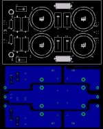
I just finished with DX HDII Clone PCB Design.
I Used Original schematics, but the Amplifier PCB is redesign.
Power Supply PCB Layout is slightly changed (As shown in figure.
Here I am posting DX HDII Power Supply Board images, tomorrow I will post Amplifier PCB images.
-suds
hello,
I just finished with DX HDII Clone PCB Design.
I Used Original schematics, but the Amplifier PCB is redesign.
Power Supply PCB Layout is slightly changed (As shown in figure.
Here I am posting DX HDII Power Supply Board images, tomorrow I will post Amplifier PCB images.
-suds
Attachments
I'm certainnly not speaking for Carlos...
Suds:
I'm certainnly not speaking for Carlos, but I would think one of the design elements of the snubbers (let's use C3 as an example) across the electrolytics (C7) is to be as close to the actual pins of the big caps as possible. I can see why you would move them around cosmetically, and you did a very good good with the boards. But, personally I think you should at least move any snubbers back to their close-up positions with their mates. In this case, it could mean mounting them on the bottom of the board.
Just my 2 cents.
")
Suds:
I'm certainnly not speaking for Carlos, but I would think one of the design elements of the snubbers (let's use C3 as an example) across the electrolytics (C7) is to be as close to the actual pins of the big caps as possible. I can see why you would move them around cosmetically, and you did a very good good with the boards. But, personally I think you should at least move any snubbers back to their close-up positions with their mates. In this case, it could mean mounting them on the bottom of the board.
Just my 2 cents.
Should be ok for 8 ohm loads... I would however swap the 16V zeners for 15V ones just to keep the regulation headroom.
Feel the transformers for overheating over a period of time and see how they handle it...
Worst case scenario you sit with a working amp and a transformer that needs an upgrade at some point in time... I think for average listening levels it should work fine.
just to give you an idea of scale one 180VA transformer is normaly good for a 20W x 2 amp, maybe a smidgen more if the amp is reasonably efficient.
- Status
- This old topic is closed. If you want to reopen this topic, contact a moderator using the "Report Post" button.
- Home
- Group Buys
- Destroyer x Amplifier DX HDII version.