aluminum nitride
It is a very good conductor of heat. It is made into insulator pads for mounting devices to heat sinks. Get the right size...the material is very tough, a beach (sp?) to cut without the right tools.
http://www.accuratus.com/alumni.html
It is a very good conductor of heat. It is made into insulator pads for mounting devices to heat sinks. Get the right size...the material is very tough, a beach (sp?) to cut without the right tools.
http://www.accuratus.com/alumni.html
leach amp pcb
Hello Forum,
I'm new to this, both to Forum usage and to diyAudio. I would be interested to participate in a group buy of Leach amp PCB's. I need 4 of them (actual transisitor count is not essential, I'll conform to the preference of the majority). I hope somebody out there can help me.
Regards,
Rembert
Our boards
I just received an email from Advanced Circuits. The pcb's shipped out this Friday afternoon. Just a small update. We should all be getting our new toys soon. I also want to take this time to add credit to those who requested the boards and followed through with the purchase. When several total strangers get together and pull something like this off it reinforces my faith in humanity. Thanks Tad
I just received an email from Advanced Circuits. The pcb's shipped out this Friday afternoon. Just a small update. We should all be getting our new toys soon. I also want to take this time to add credit to those who requested the boards and followed through with the purchase. When several total strangers get together and pull something like this off it reinforces my faith in humanity. Thanks Tad
Re: Leach amp boards
Great! Do you have any pictures?
Thanks Tad!
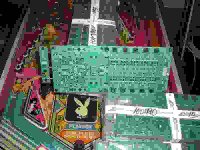
tryonziess said:The boards arrived today. The first batch should be in the mail by noon tomorrow. They look real good. Tad")
Great! Do you have any pictures?
Thanks Tad!
Re: Re: Leach amp boards
X2
dudaindc said:
Great! Do you have any pictures?
Thanks Tad!
X2

Hi,
I'm not the one to ask, I still get variable results from it depending on which order I click the options. I don't understand what it does and that stops me being efficient with it.
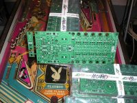
A plain background would reduce the bit count and get more detail into the PCB while staying within the 100kb & 999x999 pixel limits.
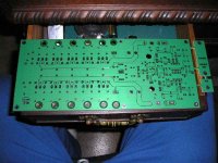
I wonder if this PCB is the version with the corrected NFB return route? A pic of the back would tell all.
I'm not the one to ask, I still get variable results from it depending on which order I click the options. I don't understand what it does and that stops me being efficient with it.
A plain background would reduce the bit count and get more detail into the PCB while staying within the 100kb & 999x999 pixel limits.
I wonder if this PCB is the version with the corrected NFB return route? A pic of the back would tell all.
Hi,
you're going to hate me even more for this, but it looks like this PCB needs the NFB to be modified to run a wire from the output connection into the cut track that taps into the wrong end of the output trace.
I did point this out in the thread (post59), re choosing the correct layout.
you're going to hate me even more for this, but it looks like this PCB needs the NFB to be modified to run a wire from the output connection into the cut track that taps into the wrong end of the output trace.
I did point this out in the thread (post59), re choosing the correct layout.
AndrewT said:Hi,
you're going to hate me even more for this, but it looks like this PCB needs the NFB to be modified to run a wire from the output connection into the cut track that taps into the wrong end of the output trace.
I did point this out in the thread (post59), re choosing the correct layout.
Andrew,
I will be most surprised if you ever tested this and verified that you can tell the difference of different pick off points for the NFB (in this design or any other) in a double blind test.
This design works just fine the way it is, and although the theory behind you claim is ok, I find it totally uncalled for that you bring this modification up every time you see the layout.
Not only do you question the decisions I made during the PCB design, you also let all the builders (and maybe Tad) worry about something that is of minor importance to the overall result. I find this most unacceptable as you time and again have proven that you are more than willing to criticize the works of others, while you completely neglect to get your own hands dirty doing some actual design work.
When modifying the PCB with your suggested change, the builder risks a bad solder joint in the most critical place of the amp. Without the NFB connection the amp can destroy a speaker connected to the output, and that is IMHO far worse than the 0.0XX% extra THD added by a no ideal NFB pickoff point.
To all builders:
Rest assure that the PCB layout works well, and that the end result (if the amp is properly build) will produce great sound.
Tad: nice looking boards!
\Jens
Jens Rasmussen
Jens I thank you so very much for making this project a reality. To all who have purchased this board several are already in the mail to you. Thank you for your perserverance in this project.
Now I just need to make the right choices for the parts. This will take my adult toy building money for quite some time. More to do and so little time to do it. Tad
- Home
- Group Buys
- Jens Rasmussen Leach clone group buy