Luke,
That is some ways off right now. I have to make sure the smoke stays in the box before I proceed. Magic smoke --- not too good.
I also am in the process of removing five of the BCxx devices and putting in the MPSA42/92 items. Just some caution. I usually have a set of spare boards for smoke and fire issues. Not this time. Have to be real careful.
I even added the proverbial 100 ohm safety resistor to the incoming power. Aren't we getting careful these days.
Now 70+ volt rails with a very stout power supply and the 80 volt frontend should get me near 300 strong watts in 8 ohms. About what I want. Never can judge how much sag I will get.
Still have the dual mono single mono issue going on. I can not make up my mind on this. I like the symetry of dual mono. What with one board on each side and such. It will just be one big monster. 4 trannys, two huge heatsinks, 32 capacitors. That is a lot for one box.
I am getting ahead of myself. Must first contain the smoke.
The second round group buy is progressing nicely. Some of you may rethink buying some extra boards. Never know when the solder bug will bite. It is after all only money. We can always earn some more.
Tad
hi Tad,
the thing about this is to take your time. Troubleshooting can be fun, but the hassle and annoyance of blowing parts, having to source more etc can be a pain.
What I do is triple check everything.
Measure values where you can, check polarity, do one board then the same part on the other board. Visual check are they the same. Then the next one.
If you leave it overnight and then check everything again, your probably going to be ok. Where Ive allways had problems is when Ive tried to get things running quickly so as I can listen to it now, enthusiasm kills amps
")
Im sure you know all this and youll be fine.
Jens,
What is preferred? Leave them out or just leave them at 10r.
I have them soldered in and at the bom values.
I did leave out the resistors from the rail supply to the frontend.
Is there anyway to calculate what range the protection circuit begins to enable? Dr. Leach has a footnote in the original article detailing a change he made for those wanting to drive higher currents.
Jens,
What is preferred? Leave them out or just leave them at 10r.
I have them soldered in and at the bom values.
I did leave out the resistors from the rail supply to the frontend.
Is there anyway to calculate what range the protection circuit begins to enable? Dr. Leach has a footnote in the original article detailing a change he made for those wanting to drive higher currents.
Tad, just leave them out to start with... the protection circuit is likely to need tweaking aynway.
10 Ohm is bad, and will kill the small lignal resistors in the protection circuit.
\\\Jens
Jens,
Have you had anytime at all to play with this amp before you report to work?
If you have any tweaking ideas let me know and I can plug them in. I have both boards stuffed and ready to mount on the heatsinks. It is kind of bizarre the way Dr. Leach discribes the actual science behind this protection circuit anyway. More like shooting from the hip and adjusting as you go along. The actual graph has a small window of operation. Over my head!!
Enjoy the summer. Tad
Jens,
Have you had anytime at all to play with this amp before you report to work?
If you have any tweaking ideas let me know and I can plug them in. I have both boards stuffed and ready to mount on the heatsinks. It is kind of bizarre the way Dr. Leach discribes the actual science behind this protection circuit anyway. More like shooting from the hip and adjusting as you go along. The actual graph has a small window of operation. Over my head!!
Enjoy the summer. Tad
Tad,
I have just one more day with Jeppe (my 2 year old) before I start work again... right now it is 28 degrees C in the shade, and not really the ideal time for DIY audio stuff... so no I will not have a chance to build these amps any time soon.. I might however get someone to do a test build for me when I start work.... I'm sure some the apprentices would love to get their hands on a pair of amps like this one...
I have no other tweaks as of now... only testing will show if the protection circuit is ok. When the boards are mounted on a heatsink it is easy to remove a wrong resistor, simply cut it in two and remove the two halves, clean out solder in holes and adjust pins of new conponent then solder.. plated though holes will ensure that the new solder flows through the board and makes excelent contact on both sides.
Have fun!
\\\Jens
the protection circuit is triggered when the Vbe that is present turns on the protection transistor.
Most transistors are near enough Off when Vbe<400mV (but not all).
Most transistor are working well with low resistance across CE when Vbe is between 500mV and 700mV.
Most transistors are saturated when Vbe>750mV. In this state the Vce can be less than 100mV.
I can see that any protection transistor that has >400mV applied is starting to turn on. i.e. it starts affecting the output signal coming from the VAS to the driver.
I can also see that when Vbe >750mV that almost all the drive from the VAS to the driver has been diverted through the protection transistor to the output rail. Be careful you have protected the VAS from damage.
With that range of triggering voltage it only makes sense that resistor settings and triggering voltages are intimately correlated.
In my view any protection system must pass all valid audio signals to all valid speaker loads. This implies that Vbe of the protection transistor must be much less than 600mV, when a valid audio signal is required to pass to the output.
I can see an argument that it should be below 400mVbe.
Everything around the output stage affects the voltage sent to the protection transistor. Starting with the mains voltage fed to the transformer and ending with the phase (leading/lagging) of the load.
I cannot see how we can provide a universal set of resistor values for a random amp assembly.
Last edited:
I cannot see how we can provide a universal set of resistor values for a random amp assembly.
Amen
\\\Jens
In closing, if we were building identical copies of the debugged demonstration version then there is no problem determining the resistor values. Then testing that we have calculated correctly and that it still sounds right when extreme audio signals are sent to extreme, in specification, speakers.
That is exactly what happens to get a product ready for the production line.
Here we are DIYing. Everyone's build will be different.
That is exactly what happens to get a product ready for the production line.
Here we are DIYing. Everyone's build will be different.
It might be a good time to add a little fuse in each of the outputs. This is a robust amplifier and as such will have the ability to weld a nice set of speakers. My next addition.
I will leave all of the tweaking and discrete component design to more knowledgeable folks.
Jens, Nice little project to carry with you on your first day at work. No meager project this one. The good stuff.... And by the way those little regulators work like a champ.
Tad
I will leave all of the tweaking and discrete component design to more knowledgeable folks.
Jens, Nice little project to carry with you on your first day at work. No meager project this one. The good stuff.... And by the way those little regulators work like a champ.
Tad
Testing Rasmussen-Leach board assemblies
Hi All.
After an unsuccessful search, I now am wondering if there is a need for another thread devoted to testing and trouble-shooting these Rasmussen-Leach PCB assemblies? Or does anyone here know of another thread devoted to sorting out these assemblies?
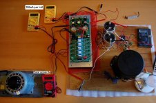
Below is a pic of one possible test setup, where we used a variac to adjust voltage, light bulb to current limit, and several cheap ($2 @ HarborFreight) DVM's to monitor everything. I like this, as we can see operating voltages/currents instantaneously, as we adjust settings...
-Chas
Hi All.
After an unsuccessful search, I now am wondering if there is a need for another thread devoted to testing and trouble-shooting these Rasmussen-Leach PCB assemblies? Or does anyone here know of another thread devoted to sorting out these assemblies?
Below is a pic of one possible test setup, where we used a variac to adjust voltage, light bulb to current limit, and several cheap ($2 @ HarborFreight) DVM's to monitor everything. I like this, as we can see operating voltages/currents instantaneously, as we adjust settings...
-Chas
Attachments
Andrew wrote:
Cannot find it. If not too much trouble, can you please post the url.
Thanks,
-Chas
there used to be a sticky thread for Leach amp problems/solutions.
Cannot find it. If not too much trouble, can you please post the url.
Thanks,
-Chas
here's one - http://www.diyaudio.com/forums/soli...shooting.html?highlight=leach+troubleshooting
What problem are you having? The pictured amp seems to be idling fine.
What problem are you having? The pictured amp seems to be idling fine.
Regulation/separate supplies for 3 amplifier stages
I have an interest in providing separate supplies to the stages
of Jen's Leach amp and regulating the input stage.
Is it worth doing if I have the available supply rails?
I have transformer with taps at 32.5vac, 37vac and 40vac.
For the lower voltage tap I have a suitable 40vdc regulator
(which accepts 32-35vac) to replace the Zener supply.
When rectified and filtered the other taps provide 52-0-52vdc
@1.5A and 56-0-56vdc @3.2A,respectively.
How can these voltages be used to provide separate and stable
individual voltage supplies to each stage with Jens Board?
At what points in the diagram and where on the boards
should the VCC and VSS traces be cut to do this?
TIA,
-Chas
Attachments
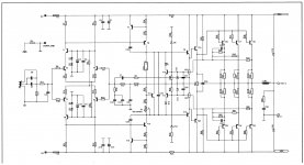
Vc is the second power supply. Vcc supplies both ends via the fuse then R1 to the front end. Simply omit r1 and you have a twin power input.
If you read Jens' description, he tells you all.
32.5Vac is a bit low for regulated 40Vdc.
I suggest you use the 37Vac tapping and get a regulator that can accept 37+20% Vac as the maximum input voltage.
If you read Jens' description, he tells you all.
32.5Vac is a bit low for regulated 40Vdc.
I suggest you use the 37Vac tapping and get a regulator that can accept 37+20% Vac as the maximum input voltage.
Note that the VAS is connected to Vc and Vs when you remove R1 and R23. If you limit your front end to 40V, you won't be able to swing full output rail voltage. Not that you'll hurt anything, but you will waste energy in the outputs and limit your output voltage swing.
Your best bet is to have the regulated front end voltage approximately the same as the output voltage, maybe a volt or two higher.
You can separate the VAS if you really want to by cutting traces to isolate T7 and R24 as well as T15 and R35. You'd probably want to add local decoupling (like C1, 2,14 and 15). Seems like an awful lot of trouble for minimal gain.
BTW, your transformer is a bit light unless it's just for one channel. You'll probably be OK for "normal home use" - maybe a few watts RMS output, but you won't be able to drive full power for long.
- Home
- Group Buys
- Jens Rasmussen Leach clone group buy