I bet there's more buyers for the boards out there and more that have read this thread that have not signed the WIKI yet. So if you're out there, get off the dime and put you two cents down on the WIKI.
Maybe just a "one liner" in the Trading Post and Solid State about the boards with a link to the WIKI would catch a few more buyers and get the ball rolling.
Maybe just a "one liner" in the Trading Post and Solid State about the boards with a link to the WIKI would catch a few more buyers and get the ball rolling.
Attachments
Board Quote
Quote on boards from Advanced Circuits for 50 boards is 18.43. If we can get to 100 boards the price drops to 15.50. This does not reflect shipping costs to me or shipping to you. This is just the per board price on quote.
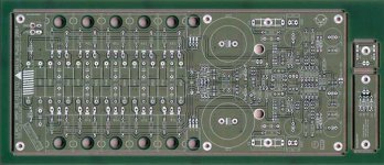
The 10 transitor board is quite long which makes them cost somewhat more. They are the thick boards with 2 oz. copper. If you look in this thread some pages back you will see a picture of the boards. They come from Advanced Circuits very well made. These are cnc cut boards not etched.
I ship them out in large U.S. Postal envelopes. Each board is wrapped up tight and secured with tape.
I believe when we get this together I will ship 2 of the babies to Dr. Leach in Atlanta so he can see how his project has progressed over the years. He is really a decent sort of guy, philanthropic with his intellectual property like papa Nelson, and should be proud of Jens work.
Bob or anyone else how about figuring some way to put Jfets in the frontend. It is also easy to run this board with separate regulated frontend the way Jens has it layed out. Tad
Quote on boards from Advanced Circuits for 50 boards is 18.43. If we can get to 100 boards the price drops to 15.50. This does not reflect shipping costs to me or shipping to you. This is just the per board price on quote.
The 10 transitor board is quite long which makes them cost somewhat more. They are the thick boards with 2 oz. copper. If you look in this thread some pages back you will see a picture of the boards. They come from Advanced Circuits very well made. These are cnc cut boards not etched.
I ship them out in large U.S. Postal envelopes. Each board is wrapped up tight and secured with tape.
I believe when we get this together I will ship 2 of the babies to Dr. Leach in Atlanta so he can see how his project has progressed over the years. He is really a decent sort of guy, philanthropic with his intellectual property like papa Nelson, and should be proud of Jens work.
Bob or anyone else how about figuring some way to put Jfets in the frontend. It is also easy to run this board with separate regulated frontend the way Jens has it layed out. Tad
One thing that gets people rolling is a deadline. I was always amazed at how many people signed up at or just after the deadline on my buys. ")
This is an excellent implementation of a solid design. You won't be disappointed.
Great idea to get a pair for Dr. Leach. He took the time to answer my questions on my first build like I was in his class.
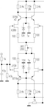
Jfets might require a bit of surgery. Half of the front end is cascoded, but to use jfets you'd need to cascode both legs of the differential to keep from frying them. I can see with two cut traces and a cascode placed at R3 and a flying lead to its base.
edit: or cut the trace on the bottom between R3, T3 and T1 (T5, T6, R22). Insert a cascode transistor on the bottom - wouldn't look like a Frankenboard from the top. Remove R5 and R22, tie the two differentials together with a resistor or trimpot using the open pads.
You'd need to separately power the VAS if you were thinking of dropping the differential voltage to allow the jfets to live - another couple of cut traces.
Interesting idea - I may have to add more boards to my order for an experiment. Darn you!
This is an excellent implementation of a solid design. You won't be disappointed.
Great idea to get a pair for Dr. Leach. He took the time to answer my questions on my first build like I was in his class.
Jfets might require a bit of surgery. Half of the front end is cascoded, but to use jfets you'd need to cascode both legs of the differential to keep from frying them. I can see with two cut traces and a cascode placed at R3 and a flying lead to its base.
edit: or cut the trace on the bottom between R3, T3 and T1 (T5, T6, R22). Insert a cascode transistor on the bottom - wouldn't look like a Frankenboard from the top. Remove R5 and R22, tie the two differentials together with a resistor or trimpot using the open pads.
You'd need to separately power the VAS if you were thinking of dropping the differential voltage to allow the jfets to live - another couple of cut traces.
Interesting idea - I may have to add more boards to my order for an experiment. Darn you!
If I can get a suitable up front order I plan on buying 20 or 30 extra to fill the "johnny come lately" crowd.
Two inputs on the jfet theme, now we are going in the right direction. Is it worth the effort? Would standard mosfets make any difference in the frontend. They come in suitable voltage ranges. Tad
Order as many boards as you need.
Two inputs on the jfet theme, now we are going in the right direction. Is it worth the effort? Would standard mosfets make any difference in the frontend. They come in suitable voltage ranges. Tad
Order as many boards as you need.
Just swapping in mosfets for the inputs might work. I have a bunch of ZVN3310 and ZVP3310 that a few seemed to like in the Aleph series. I should have some building time available this weekend, I'll try it.
To get the "bleedin hot" front end, you'd want to decrease the values of R5 and R20 to increase the bias (a Krell like constant current diode might be an idea here). Not sure how much you'd want to increase the differential current with ZVN/P3310 but 10-20 mA for the pair its in my brain - I'll look into it after work, (from which this thread now has me totally distracted)
Substituting mosfets in the cascode, VAS and driver is more problematic as there isn't a way to get gate stopper resistors in there without cutting traces. You'd also need to adjust the VAS protection to account for Vgs>Vbe.
Bob, We are talking about the current 10 trans board, right? And you needed a distraction from all that work anyway. Beats golf.
Now if Jens would modify the board for say the mosfet frontend, whoa dude! Could we expect any type of sound improvement or are we just playing diy audio here? This is already a hard act to follow. Tad
Now if Jens would modify the board for say the mosfet frontend, whoa dude! Could we expect any type of sound improvement or are we just playing diy audio here? This is already a hard act to follow. Tad
Tad, I was referring to frankenboarding the current 10 transistor version. A couple hits with a dremel tool and you are ready for JFETS.
Mosfet front end (limited to the four devices in the differential pair, the cascode remaining a bipolar device) is a matter of plugging in the devices and changing a couple of resistors to increase the bias. I'm going to reduce the degeneration resistor (in emitter legs of the differential) to 220R for two reasons - ensure I have enough gain and, more importantly, I have them on hand but not 330R. I'll also reduce the gate stoppers (R6, R7, R18 and R19 to 220R for the same reason.
I also have a few matched sets of output Mosfets ...
As for sound improvements, who knows? I like the sound of my A75 a little better than my Leach by a small margin - but not enough to put up with the heat load of the A75 in the summer. Is it the mosfets or the folded cascode topology?
Professor Leach didn't care for the sound of Mosfet output devices, but didn't elaborate on his implementation. If he biased them the same as the standard version, it would explain a lot. Pass suggests 100 mA per device as a minimum, and the standard Leach bias is around 110 mA total. I biased mine at 125 mA which improved the top end slightly.
Fred: this is the same board as Tad's last GB.
What might seem like a dremel here a solder there is rocket science to me at this stage. One day!! I think Dr. Leach was using early 1970 era mosfets and jfets. I do not think they were anything like the Toshiba and Fairchild units of today. Silicone has come a long way. Just look at Hollywood. Tad
Group Buy Round 2
O.K. Folks.
I will place an order for the boards Friday afternoon. I plan to prepay for these myself. The price for the boards will be 17.00 U.S. each PLUS shipping. In order to get this price I chose the 4 week delivery option. Advanced Circuits made the last boards which I was quite happy with. I plan on using them for this purchase. If your name is on the Wiki for this project you will receive your pcb's. There are only 90 slots available so if you have not signed up this is your notice. Do not miss out on this great amplifier.
If the number of slots exceeds 90 by order time I will of course increase the number ordered.
You need to send me a confirmation E-MAIL with your Name, Address, method of payment, and number of pcb's you will require. I will send you an email with the exact cost plus shipping. There is a 3 percent charge also added for paypal users.
My email is tadellis@bellsouth.net
I am prepaying for the boards and would appreciate payment before the boards arrive to me. Tad
Things seem to be moving along quite nicely now with the email, address etc. coming in to my address.
As I posted earlier an exact price for the boards and shipping will be sent to you after I place the order.
Remember if for some reason you can not send payment by paypal I will gladly except Western Union, U.S. Postal, money orders.
I can take personal checks but would rather not get involved with that. O.K.
If you know of someone else who might be interested in this group buy get them involved. The more boards we order the better price we can get.
Important This is a hobby only diy thing. Let us not find these boards up for sale on EBAY for profit. Dr. Leach and Jens Rasmussen put a lot of effort into providing us with there intellectual property for free. O.K.
For those of you who might begin purchasing the parts to build this amp the B.O.M. is on the Delta-Audio.com website.
Jens has provided the dimensions for some of the parts on the B.O.M. I found that some of the DALE RN resistors are rather large for this build. Some of the holes which were specified the proper size actually were a little tight once they were plated. If you reproduce the layout to scale on your printer you can get a pretty good idea what will fit in a particular area before you purchase the parts. Also, Jens uses plastic standoffs and not metal which might be a problem to some - (I did not have any) - because the area around the mounting holes is Ground. Just a few ideas. Bob if I missed something please jump right in.
Tad
As I posted earlier an exact price for the boards and shipping will be sent to you after I place the order.
Remember if for some reason you can not send payment by paypal I will gladly except Western Union, U.S. Postal, money orders.
I can take personal checks but would rather not get involved with that. O.K.
If you know of someone else who might be interested in this group buy get them involved. The more boards we order the better price we can get.
Important
This is a hobby only diy thing. Let us not find these boards up for sale on EBAY for profit. Dr. Leach and Jens Rasmussen put a lot of effort into providing us with there intellectual property for free. O.K.For those of you who might begin purchasing the parts to build this amp the B.O.M. is on the Delta-Audio.com website.
Jens has provided the dimensions for some of the parts on the B.O.M. I found that some of the DALE RN resistors are rather large for this build. Some of the holes which were specified the proper size actually were a little tight once they were plated. If you reproduce the layout to scale on your printer you can get a pretty good idea what will fit in a particular area before you purchase the parts. Also, Jens uses plastic standoffs and not metal which might be a problem to some - (I did not have any) - because the area around the mounting holes is Ground. Just a few ideas. Bob if I missed something please jump right in.
Tad
Good point about isolating the mounting holes.
To save a little hassle, the fuse holders are 5x20 mm, not the more common in the US 3ag. Digikey and mouser both have them, I'll see if I can dig out the part numbers.
I've used the Vishay/Dale CW series for the emitter resistors on these boards. (RS and NS are the same body size) Yes it is a tight fit, careful bending of the leads is required. If you try to put a bent lead through the holes, you'll likely have to pull it with pliers.
To bend the leads past the body comfortably you'll end up with a little more length than the spacing between holes. A little overbend and bend back and you have a nice standoff that helps air circulation. You may want to use standoffs, but I don't see a real need.
I haven't tried to use high end resistors for the 1/4 or 1/2 watt positions.
Nichicon Muse 470 uf bipolars won't quite fit.
If you're planning rails more than 75V, it's probably a good idea to use MPSA42 and MPSA92 for the front end, just remember to reverse them, since the board is laid out for BC5x6.
Yes, this buy is of Jens' original update of the Low TIM Leach amp. I wouldn't call it low powered, with 5 MJL4281/4302 pairs you could run 80-90 volt rails comfortably for well over 200W into 8 ohms.
The newest version with a detached "universal" Low-TIM/Double barreled (AKA Superamp) front end and either extended (10 devices) or double barrel (16 devices) output boards is being prototyped.
The double barrel superamp was developed for higher power operation with devices that were available at the time. Cascoding the outputs required cascoding the drivers and VAS, which is probably the reason that some prefer its sound to the Low TIM. I haven't built one , so I don't know (yet).
- Home
- Group Buys
- Jens Rasmussen Leach clone group buy