In a thread within the last month or so, someone posted a design for a small Karlson slot cabinet for a Fostex FE167E. I've been searching for it but cannot find it now.
I'm just curious if anyone knows where the design is? Also, has anyone tried it? I've never heard a Karlson and was curious how it sounds.
Thanks
I'm just curious if anyone knows where the design is? Also, has anyone tried it? I've never heard a Karlson and was curious how it sounds.
Thanks
Go here http://fullrangedriver.com/gallery/thumbnails.php?album=1
I came across it while looking for his FE126E enclosure.
I came across it while looking for his FE126E enclosure.
good...
The cabinets have only some 1/4 inch felt inside the line and the tapers have been modified. with a good amp they make credible bass but most would want to run subs with them. Laying them on thier sides can generate spectacular image and stage. Am running the FE166E with some mods you can ground the top plate for good results. Took them to Denver a few years back to the RMAF and surprised a few people. Would make the line plus coupler length a 1/4 wave of driver Fs when I build another pair. New coupler tapers looks like a tractrix curve and stops shor of the top of the driver on the canted baffle. My existing tapers close up to 3/8 inch gap, could experiment with smaller gap might be worth while. Build the cab so the tapers can be easily exchanged for experimentation. Regards Moray James.
The cabinets have only some 1/4 inch felt inside the line and the tapers have been modified. with a good amp they make credible bass but most would want to run subs with them. Laying them on thier sides can generate spectacular image and stage. Am running the FE166E with some mods you can ground the top plate for good results. Took them to Denver a few years back to the RMAF and surprised a few people. Would make the line plus coupler length a 1/4 wave of driver Fs when I build another pair. New coupler tapers looks like a tractrix curve and stops shor of the top of the driver on the canted baffle. My existing tapers close up to 3/8 inch gap, could experiment with smaller gap might be worth while. Build the cab so the tapers can be easily exchanged for experimentation. Regards Moray James.
yes...
I built seveal sets with both the 167 and the 166 and they both work well in this cab. The 167 was a little better in the bass than the 166. As I said I would adjust the line length to include the coupler length into the overall length for 1/4 WL at Fs (so make the back line shorter). You want the total line length from back of driver to front of driver to be 1/4 Fs.
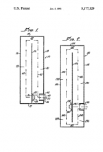
Interesting food for thought can be found in the Klayman US patent number 3 047 090 use Google patent search. The second drawing in this patent is especially interesting. Regards moray James.
I built seveal sets with both the 167 and the 166 and they both work well in this cab. The 167 was a little better in the bass than the 166. As I said I would adjust the line length to include the coupler length into the overall length for 1/4 WL at Fs (so make the back line shorter). You want the total line length from back of driver to front of driver to be 1/4 Fs.
Interesting food for thought can be found in the Klayman US patent number 3 047 090 use Google patent search. The second drawing in this patent is especially interesting. Regards moray James.
Attachments
"Laying them on thier sides can generate spectacular image and stage. "
Moray -- This is intriguing - why might this be the case?
How do you find the imaging/staging with the K-slot loading compares to the more typical direct radiating applications for these drivers?
Thanks for your thoughts, JF
Moray -- This is intriguing - why might this be the case?
How do you find the imaging/staging with the K-slot loading compares to the more typical direct radiating applications for these drivers?
Thanks for your thoughts, JF
As I said I would adjust the line length to include the coupler length into the overall length for 1/4 WL at Fs (so make the back line shorter). You want the total line length from back of driver to front of driver to be 1/4 Fs.
I need some help here since I have no design experience at all.
The Fs of the Fostex FE167E is 51.5hz. That works out to be roughly 65 1/2 inches.
How do I measure the line length so that it includes the coupler length? The line in red on the attached image is my best guess. It works out to be somewhere between 36 and 40 inches (based on a 1:3 scale in the plans and using a ruler to measure). This means I need another 20 inches or so.
I'm doing something wrong, please let me know what I'm missing.
Attachments
Thid drawing...
was developed for the FE127. If you look at the drawings posted in this thread you will see the cabinet designed for the FE166/167. In that cabinet the line enters the coupler at the to of the cabinet. That is where I would place it for the 126/7. So what driver do you want to use?
was developed for the FE127. If you look at the drawings posted in this thread you will see the cabinet designed for the FE166/167. In that cabinet the line enters the coupler at the to of the cabinet. That is where I would place it for the 126/7. So what driver do you want to use?
Now I'm really confused...
I have the Fostex FE167E drivers.
The drawing I posted with the red lines started as a screen shot of this pdf in the FullRangeDriver Gallery. The diagram says that its for the FE167E.
Here's a couple of newbie questions - I was assuming I knew the answers but now I'm not sure.
* Isn't the "line" the path from the rear of the driver to where the sound can escape?
* What is the "coupler"?
Thanks again.
Sorry too many drawings...
my fault. The drawing that is posted above is an older one. The design was modified moving the terminus from just above the driver to the top of the cabinet. The best way to visualize it is if you were to take the top most section of the curved reflector and place below covering where terminus vent shows in the drawing posted here (the PDF drawings). The coupler section is the cavity in the front section of the cabinet and is comprised of the curved reflector section and the entire cavity that extends down to the driver. This is the section that also includer the Karlson tapers (the horn shaped opening on the front panel). I hope that this is making sense. So the actual line length is comprised of the section that zig zags up the back side of the cabinet (from the driver) up into the top of the coupler section and down to the front side of the driver. The entire line should be a 1/4 WL from the back of the driver to the centre front of the driver. Are you following this now?
my fault. The drawing that is posted above is an older one. The design was modified moving the terminus from just above the driver to the top of the cabinet. The best way to visualize it is if you were to take the top most section of the curved reflector and place below covering where terminus vent shows in the drawing posted here (the PDF drawings). The coupler section is the cavity in the front section of the cabinet and is comprised of the curved reflector section and the entire cavity that extends down to the driver. This is the section that also includer the Karlson tapers (the horn shaped opening on the front panel). I hope that this is making sense. So the actual line length is comprised of the section that zig zags up the back side of the cabinet (from the driver) up into the top of the coupler section and down to the front side of the driver. The entire line should be a 1/4 WL from the back of the driver to the centre front of the driver. Are you following this now?
How's this...
I've edited the image I posted above, moving the curved reflector down and allowing the terminus of the pipe to come out the top. Please let me know if this is what you meant.
With regard to the Fs value and line length. I did some reading last night and found a suggestion that drivers with a Qts below .35 should add 10Hz to their Fs value (is this is what is meant by tuning?).
Based upon that suggestion, the Fs would be 61.5Hz, the wavelength would be 18.3 feet so the line length would be 54 7/8 inches.
PS. If you already have some plans or pictures please post them.
Attachments
Close...
I would calculate fromthe point where the voice coil meets the cone. Further I would simply drop straight down from where the line meets the coupler to the cone/voice coil. As you can see the cabinet internals can be adjusted to make use of the space that is not being used due to the changes but you get the idea.
can you post the url where you read about adjusting the Fs as a result of Q? Seems to me that the Fs is the Fs regardless of the driver's Q. Not something that I have made adjustments for in the past but i would be interested in having a look at the text.
Sorry I only have working plans nothing was formally drawn up fo this version.
So, is the basic layout of the diagram correct?
If so, I will calculate the line-length starting at the back of the cone/voice-coil, going through the zig-zag pipe, coming out at top of the cabinet and then coming straight down to the cone/voice-coil again.
If that's right then I believe the line length will need to be somewhere between 55 and 65 inches depending upon the value of Fs used (61Hz or 51Hz). Still haven't gotten a confirmation that I am calculating this correctly. I'm guessing on a lot of this stuff. I'm basing the length of the line off of the wavelength calculator found here .
The Fs adjustment is in the Pearls from Martin J. King Quarter Wave Design article. Scroll down to the Driver Thiele-Small Parameters section and it says:
Then below that in the Starting point section it says:
Of course, the next question will be about the front of the enclosure - where to start the cutout, what radius to use, etc. Thanks for your help.
If so, I will calculate the line-length starting at the back of the cone/voice-coil, going through the zig-zag pipe, coming out at top of the cabinet and then coming straight down to the cone/voice-coil again.
If that's right then I believe the line length will need to be somewhere between 55 and 65 inches depending upon the value of Fs used (61Hz or 51Hz). Still haven't gotten a confirmation that I am calculating this correctly. I'm guessing on a lot of this stuff. I'm basing the length of the line off of the wavelength calculator found here .
The Fs adjustment is in the Pearls from Martin J. King Quarter Wave Design article. Scroll down to the Driver Thiele-Small Parameters section and it says:
I use a Qts value of 0.35 to distinguish between high and low Qts.
Then below that in the Starting point section it says:
A starting point could be to tune the enclosure 5-10 Hz above the driver's Fs if it is a low Qts driver. Tune the enclosure 5-10 Hz lower than the driver Fs, if the Qts is high. However, this is a guideline only.
Of course, the next question will be about the front of the enclosure - where to start the cutout, what radius to use, etc. Thanks for your help.
yes...
your basic layout is correct. Tunning suggestions from MJK sound good to me.
Regarding the tapers as I mentioned I ended up with tapers that looked like a tractrix expansion with the tapers flairing out to the edge of the cabinet at the top edge of the driver cone. They started at the top of the cabinet at 3/8 of an inch wide. You might try a radial taper based upon the circumference of the driver as the radius used for the radial taper. I have no hard answers for you. I can say that I was not thrilled with the radial tapers that I used.
The height of your cabinet may well vary from that I chose to work with which was about twice the driver diametre. since this a line that is 1/4 WL long and since it folds over onto itself you cannot go any higher (cabinet height) than half of the WL you chose for your tunning frequency. At this point I think that you will have to go with your intuition and build what you think is best and then simply learn from your mistakes. Make the tapers removable and try as many as you like. I built quite a few then resorted to using plastercine to make experimental curves and to play with the spacing at the top of the tapers. This was easy and fast to do. I ended up with the curves that I did a through a combination of experimentation and guess work based upon my experimental findings. I will be interested in your findings.
I will say again that the best results that I have had have been with no stuffing in the line just 1/4 inch felt linning to eat up reflections of higher frequencies in the line. Damping (stuffing) the line just ate efficiency and ate up the bass. I hope that this helps. Don't be afrade to make mistakes as there are no mistakes just opportunities to learn what does or does not work.
- Status
- This old topic is closed. If you want to reopen this topic, contact a moderator using the "Report Post" button.
- Home
- Loudspeakers
- Full Range
- Searching for FE167 Karlson Design