I have been working with paper cones. I have not shared much because they are difficult to work with and easy to make fatal mistakes while modifying.
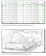
Anyway, just for illustration I am going to post a few things about the Aurasound NS3-194. This paper cone, "phase" plug transducer is still available.
In stock condition it has a sound of its own. It is a transducer that colors the sound it attempts to reproduce. That is not a reason to love or hate this transducer because most other transducers do the same.
It suffers from multiple cone vibration modes. That is why it colors the sound it tries to reproduce.
The most effective way to change the cone material vibration modes is to locate the origin points for the modes and then change the material structure in those specific locations.
Adding mass or coatings is an ineffective way to change the material structure. Many have tried (and still do try) adding mass and coatings, few have succeeded.
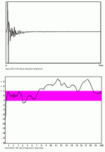
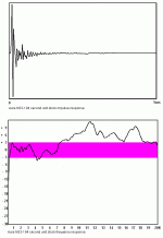
To this first post I have attached impulse and frequency response results for the stock NS3-194. The frequency response generally agrees with another poster to this forums tests. That other person's tests, however, have tended to underestimate the magnitude of vibration modes and overestimate the high frequency performance of transducers.
Anyway, here is stock performance.
Attachments
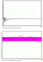
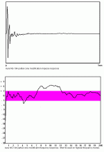
By changing nothing more than the mechanical imped of the cone material at specific locations, you can change the response in the following ways.
Because this transducer has multiple vibration modes, more area of the cone must be changed. Still, the area of the cone involved is less than four percent of total area. I have left the stock plug as is. No equalization or notch filters are used.
The high frequency shelf is the product of three vibration modes blending together. These modes can be controlled to the point where the shelf is eliminated.
The modified response is slightly better than plus or minus 6 dB by the resolution of these tests. Since that other posting of results for this driver showed better than plus or minus three dB in stock condition, the modified results by that testing resolution would be significantly better than plus or minus three dB. This just illustrates that you need to be careful when interpreting test results. Not all are made at the same resolution.
Modified, the transducer's impulse and frequency response is not as good as a Jordan, but it is close.
Attachments
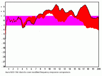
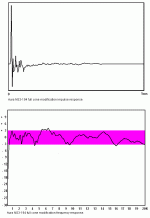
This post just illustrates the before and after difference in the performance in a graphic way. Resolution and scale are the same as in the previous two posts.
Please note how close the two tests results are in magnitude below 2 kHz. No mass has been added to the cone. There has been no change in sensitivity or in T/S specifications.
Please note how close the two tests results are in magnitude below 2 kHz. No mass has been added to the cone. There has been no change in sensitivity or in T/S specifications.
Attachments
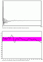
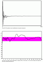
This last post is the danger post. Remember that less than four percent of the cone area is involved in the modification. You can easily, with just an unintentional slip or misplacement both improve and damage the reproduction quality.
Here a very small additional change has created a new and complex peak and dip in the response where there previously was no problem.
A successful modification of a transducer does not produce new problems. It is very easy to produce new problems when working with paper diaphragms. Therefore, I do not recommend modifying paper diaphragms as a do it yourself project.
Far better to come at diy loudspeakers as a long time learning process. Buy the best performing transducers you can find and learn acoustical theory, learning acoustical testing procedures, and learn enclosure design and enclosure testing before attempting transducer modifications.
Attachments
I am very appreciative of this cautionary tale. I have often looked at driver mods and wondered what the modder is truely accomplishing. As most don't have much for measurement equipment, and many don't even have a pair of unmodded drivers to compare. It would seem easy for them to believe the driver had been improved when it may have actually been damaged. We're talking about irreversible mods to expensive things. I have been tempted to attempt cone mods, as so many claim good luck. This post helps me follow my own logic and stick to things I can reverse or things I can simluate. Or at the very least, I will avoid messing with more expensive drivers.
pj
pj
We do not all share the same skills. I am not competent at everything that I want to do. For example, I wanted to check out anli's unix based qloud analyzer. I know very little about linux and I am not proficient with the command line interface. I am struggling to increase my competence in both areas. Going into it I knew it wasn't going to be easy for me. After all, this is not my first experience with the command line interface. I was an early owner of the Amiga computer and stayed with it for a long time. The command line was something I had to deal with and it was never a joy.
To sum, I knew what I was getting into when I started. The point of this thread is to provide some information about the difficulty and pitfalls of transducer modification that has not been talked about by too many other modifiers. Also, those other modifiers have provided very little evidence of the success or failure of their mods other than their personal testimony. Even a superficial review of posts to this forum will show a need for caution in regard to personal testimony. Further, many of the mods mentioned are not undoable. If you do and it was the wrong thing to do, then the transducer is ruined. This ought to be a concern if the modification is of an expensive transducer.
Also, you can tell a lot about the member by what they choose to call themselves. My advice is to not ignore this revealing piece of evidence.
Okay, so first for this post, I have attached the stock performance of a second unit of the NS3-194 transducer. There is some unit-to-unit variability but they you can still tell that they are the same transducer. I want to provide a little additional information about the complexity of cone material vibration modes in paper.
Just FYI, I am using a linux shell for running the browser app. I am slowly moving toward installing the necessary parts to run qloud.
Attachments
Sometimes the vibration mode is isolated and is easy to control. That is the case for the highest center frequency vibration mode. You can successfully control this mode with very little consequence.
The are four primary vibration modes. The other three are more tightly coupled and are harder to control without messing things up.
I have attached the impulse response and frequency response with the highest center frequency vibration mode control to this post.
With this top mode controlled, we have a better view of a couple of the other modes and we can see that there was some minor cancellation between the top mode and the 7 kHz mode. Control the top mode and the 7 kHz mode has slightly increased in magnitude.
Now, the origin points for the two modes are not close together, but they are still slightly coupled.
Attachments
Trying to control the 7 kHz mode is more difficult. I know exactly where its origin point is and what is beginning motions are. That does not mean I know what I can do about it.
Anyway, this posting shows what should have been the appropriate corrective, but turned out not to be. (Again, more information on the correctives will be published by the US Patent office later this year. For now, I will only refer you to that forthcoming document.)
You might also have heard that old truism that high frequencies are reproduced by the inside area of the cone closest to the VC former. While, as a generality, that is correct, it is not always true. Look at what happens when I change the cone structure approaching the surround ID. Oops, the extreme top end begins to go away. There is some improvement in the broad bump peak, and we begin to see better detail of two of the vibration modes, but at the cost of high frequency extension.
Attachments
The benefits of a proper cone design are best realized by the manufacturer. The benefits are real. They can be heard and they can be measured. This can be done in a manufacturing environment. Why are you allowing manufacturers to get away with selling substandard performing transducers?
The NS3-194, while using a conventional paper cone, has a cone construction very similar to other "popular" but under performing transducers. While the fibers may not come from the banana or coconut or other plant, the way those fibers are constructed into a cone are the same. Testing indicates that the construction of the cone is much more important to performance than the particular fiber used.
Anyway, I post here the first set of results for what I consider a properly designed cone. If you compare it to other transducers using the same test conditions and resolution, then it compares very favorably. If you, for example, use the newest Jordan as tested by Hobby HiFi, the frequency response accuracy is at a plus or minus 5 dB level from 300 to 20 kHz. The properly designed cone in the Aura brings it to about plus or minus 3.5 dB from 300 to 20 kHz.
Attachments
Those benefits, while difficult to implement, are universal to performance. I have attached a log freq response and phase response. The phase response follows the small signal frequency response with tails at the low and high end. This is good performance. It is much better than most transducers.
When reading frequency and phase response, try to get used to paying attention to scale. It is easy to make a particular test result look different by "playing" with scale and scale limits.
When reading frequency and phase response, try to get used to paying attention to scale. It is easy to make a particular test result look different by "playing" with scale and scale limits.
Attachments
Good morning Mark:
Another very interesting thread on how you have taking a driver and moved it to a new level. I appreciate the complexity in doing this and I also accept that it is easy to do it wrong. I am keen to understand the process of identifying the peaks and transposing them into locations on the driver surface so I can experiment with these inexpensive drivers.
This is a DIY site where most of the players are willing to share their ideas and techniques in the spirit of open source design with the goal to bring good sound to normal people. Many of the people here have planted the seed of an idea to watch the collective wisdom of the group make it grow.
I encourage you to consider sharing your thoughts and help others to follow a similar path.
Thanks for your contributions to the forum
MarkMcK said:Trying to control the 7 kHz mode is more difficult. I know exactly where its origin point is and what is beginning motions are. That does not mean I know what I can do about it.
Anyway, this posting shows what should have been the appropriate corrective, but turned out not to be. (Again, more information on the correctives will be published by the US Patent office later this year. For now, I will only refer you to that forthcoming document.)
You might also have heard that old truism that high frequencies are reproduced by the inside area of the cone closest to the VC former. While, as a generality, that is correct, it is not always true. Look at what happens when I change the cone structure approaching the surround ID. Oops, the extreme top end begins to go away. There is some improvement in the broad bump peak, and we begin to see better detail of two of the vibration modes, but at the cost of high frequency extension.
I am quite curious as to where the original point of the 7KHz is? The cone of this driver seems to be straight edged, is this correct?
- Status
- This old topic is closed. If you want to reopen this topic, contact a moderator using the "Report Post" button.
- Home
- Loudspeakers
- Full Range
- Aura NS3-194 mod benefits and dangers
