Hey guys, This is my first post here and actually my first attempt at a full range speakers other than a basic sealed/ported design.
I have alot of experience with DIY subwoofers and car audio, but now I'm looking to build a basic Transmission line enclosure.
The drivers I will be using are:
TangBand W3-665SC
Diaphram Material: Paper
Surround Material: Santoprene
Nominal Impedance: 8
DCR impedance: 6
Sensitivite 1W/1m 88dB
Frequency Response: 120Hz-20KHz
Free Air Resonance: 120Hz
Voice Coil Diameter: 20mm
Air gap Height: 4mm
Rated Power Input: 15W
Maximum Power Input: 30W
Force Factor, BL: 3.2TM
Magnet Weight: 120g (4oz)
Moving Mass: 1.45g
Suspension Compliance: 1106 MN^-1
Effective Piston Area: .0032 M^2
X-max: 1mm
Vas: 1.6L
Qts: 0.63
Qms: 6.88
Qes: 0.69
I have 4 of them and would like to use them in a bipole configuration. Now these speakers dont go very low so I thought a TL would be nice. I'm not a math whizz or anything so designing one from complete scratch would be impossible. What I'm wondering is if there is a simplified formula or program that can help me determine the boxes volume and Line length? I've searched quite a bit before this post but most of the information is over my head. I'm looking to do a basic TL to learn with and modify as my knowledge and understanding grows.
Cyburg's Needles look perfect but it's not designed for a Bipole configuration.
Thanks in advance for your help!
Bryan
Your first stop should be Martin King's website: www.quarter-wave.com
Martin is the big-gun of the TL / QWR in terms of math and modelling. It's not all initially very easy to understand, but it's worth the effort. Downloading his Classic TL alignment tables will allow you to size a cabinet accurately for your drivers. They look complicated, but they're not as bad as all that, if you can drive a calculator.
Also, Dave Dlugos's hobby-site: www.t-linespeakers.org is a mine of additional information well worth delving into.
FWIW, to be honest, you're going to be struggling to get any really meaningful LF out of a driver with an Fs of 120Hz. 85Hz will be about the limit, and it won't do that easily. Something like an MLTL will be a better bet than a regular TL.
Thanks for your input Scott. I learned quite a bit from the provided links even though the mathematics are still way over my head.
I was wondering if you could take a look at this link and tell me what you think about the TL calculator provided? Is it accurate?
http://www.mhsoft.nl/spk_calc.asp
Also, Cyburgs needle seems to be a proven enclosure. I'd really like to use that design but I'd also like to do a bipole. I understand that in order to add another driver (push-push) I'd have to double the Lines area? Also, how imporant is driver position. If I were to do the Needles would I put the rear speaker directly behind the front one on the rear baffle?
Thanks.
I am no expert on TL design, however the calculator provided in the link looks like it a simplified tool which basis it's dimensions around a generic formula, which might provide satisfactory results with a selection of drivers, but may not work with other drivers.
It simply multiplies the 1/4 wavelength of the frequency entered (usually driver Fs) by a factor of 1.25 to arrive at the length, and multiplies driver Sd by 1.5 to arrive at the driver end line area, and Sd=terminal area.
It makes no reference to the resonant magnification (Q) of the driver which is to be used (and will affect the performance considerably), nor other important considerations such as driver suspension compliance(Vas) and maximum linear coil motion (xmax).
There is no doubt that the results of building a cabinet based on this program will acheive bass extension, but the ripple and overall balance may not be optimum.
As far as I am aware, it is only recently that programs have been developed (such as Martin King's mathcad program, mentioned above) which strive to properly model TL's, and most traditional designs are a cumulation of educated estimates, experience and trial and error, but I suspect all of them considered more driver parameters than the program in the link.
Don't let all this put you off though. For a little effort you can be rewarded with a very capable speaker system, which will out perform any helmholtz resonator (ported) enclosure in the lower register.
I'm sure more experienced members here can give you better advice.
I thought it was odd that the calculator didn't ask for more parameters.
Just out of curiosity, In a TL, does it matter how the Line is placed in the box. I drew ideas here, would these result in the same characteristics if line size and dimensions were the same?
Just out of curiosity, In a TL, does it matter how the Line is placed in the box. I drew ideas here, would these result in the same characteristics if line size and dimensions were the same?
An externally hosted image should be here but it was not working when we last tested it.
There would be large differences in actual performance from the three drawings you made.
The first and third drawings are similar, i.e. a large closed box volume and a short TL. The volume would be such that little TL wave pressure would be resultant, other than at very low frequencies. The cabinets would have to be pretty tall to get a long enough path for the TL.
The second drawing is a tapered quarter wave TL, which is discussed on this forum on other threads, and is an ongoing discussion (look for TQWT, or Terry Cain in a search to find out more).
A traditional TL (like the picture in the link you gave) has the driver(s) located at the closed end of the TL, the other end is open. Although the line can be folded in an almost infinate number of ways.
I have tried to attach a picture of a likely arrangement for your bipole TL. Dimensions not included, as that's where the maths comes in!
Attachments
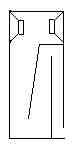
try putting the drivers on the other two sides of the enclosure you drew. This will allow them to be in the same location in the line rather than one slightly before and one slightly after.
look at the picture in this post to see graphically what I am talking about.
http://www.diyaudio.com/forums/showthread.php?postid=527384#post527384
look at the picture in this post to see graphically what I am talking about.
http://www.diyaudio.com/forums/showthread.php?postid=527384#post527384
An externally hosted image should be here but it was not working when we last tested it.
So in a design like this, Would everything in red be considered the T-Line? OR when I calculate the length would it just be the baffle thats on an angle?
I believe an accepted method of determining the exact line length is from the driver cone, to the opening at the other end of the TL. Others may give alterative opinions about this. The exact measurement is not too critical due to the fact that driver parameters vary between units, stuffing in the cabinet changes it's effective length, and the speed of sound is dependant on temperature, altitude, atmospheric pressure and humidity, all of which are continuously changing.
Since the signal propogates through the driver cone and into the cabinet, and the resulting returning wave assists or resists the cone motion, this would be logical. I suspect there would be more measurable or audible difference in different types of weather than the difference to measuring from the speaker mounting hole.
big_kahunah's suggestion of mounting the drivers on the other faces of the cabinet would ensure both drivers were identically loaded.
An interesting topic for discussion might be the affect of mounting the drivers slightly out of sync, as per my drawing.
Does anyone know of advantages or disadvantages to this arrangement?
I would imagine broader and flatter impedance peaks, making the actual tuning of the TL less critical, but I don't actually know. If the cabinet was nicely finished on all sides with the terminal plate or cable exiting from underneath, the cabinet could be placed either way around, further increasing 'tunability', i.e. mouth to front or rear.
With big_kahunah's mounting method, this could be achieved by placing the TL mouth on the same side of the cabinet as one of the drivers, mirrored for the other speaker if you are building 'stereo'.
I'm having a hard time grasping the design of the trasmission line enclosure. I understand how it works and the ending results, it's the calculations and the design process that's over my head. I noticed the quarter-wave.com site has worksheets to help map out the designs but at a 25 dollar price that I'm not willing to pay right now.
To get my feet wet, I was thinking of using exsisting designs. Unfortunately I couldn't find any bipole TL's using 2 3" drivers. I'm looking at maybe building Cyburg's Needles as a Bipole speaker. Would it make sense to double the width of enclosure to increase the Line area to accomodate 2 3" drivers?
I was also thinking of maybe Cyburg's stick and using 2, 3" drivers instead of the single 4" in a bipole configuration. The Sd of the pair is practically identical to the single 4" driver.
What do you think or what would you recommend for a beginner?
Thanks.
For an easy build, the most effective use of two 3" drivers I saw recently was a rear ported, front firing unit with the two drivers in one cabinet and a divider (two cabinets in one). The lower portion was tuned to about 50Hz? and the upper to about 100Hz? When they were pushed back into the corner, the effect was very interesting indeed. I can't say it's the best way on paper but the result was pleasing. To be honest, I barely missed having a woofer, am I'm a big woofer kind of guy. This would surely be an easy way to do it. As you can see, I'm estimating the tuning, I just stuck my ears near the ports and guessed.
IMO don't give up on the TL design. I agree, a MLTL is probably better than a TL for these drivers. Read through the reference project thread on this forum (i linked to it earlier).
Once you are able to get a design, construction is very easy and straightforward. IMO much easier than ported and only marginally more difficult than a sealed design.
Can you post the T/S parameters for your drivers and maybe we can do some computer modeling for you to help you get started.
Read through some of the projects on Martin King's website and you can sort of get the idea of where to start.
http://www.quarter-wave.com/Projects.html
I don't know if you've seen this yet, but the alignment tables are helpful especially if you don't have the mathcad worksheets.
http://www.quarter-wave.com/Theory/Alignment_Tables.pdf
I agree with big kahunah,
Don't give up yet.
The alignment tables mentioned are an easy method of ensuring a fairly predictable response.
I also agree that building TL cabinets is not at all hard. You noted that you have built sub boxes for auto installs, so an oblong TL would be very straightforward for you.
I would imagine the maths behind calculation of helmholtz resonators to be more difficult than that for TL design. Stick to a fairly convensional enclosure, and all should be well.
Big_Kahunah, Here are the T/s parameters for the drivers I have to work with.
Diaphram Material: Paper
Surround Material: Santoprene
Nominal Impedance: 8
DCR impedance: 6
Sensitivite 1W/1m 88dB
Frequency Response: 120Hz-20KHz
Free Air Resonance: 120Hz
Voice Coil Diameter: 20mm
Air gap Height: 4mm
Rated Power Input: 15W
Maximum Power Input: 30W
Force Factor, BL: 3.2TM
Magnet Weight: 120g (4oz)
Moving Mass: 1.45g
Suspension Compliance: 1106 MN^-1
Effective Piston Area: .0032 M^2
X-max: 1mm
Vas: 1.6L
Qts: 0.63
Qms: 6.88
Qes: 0.69
It's not actually the woodworking that deters me from the project, that I can more than handle. It's the mathematical equations that are way over my head. I try to read the alignment tables and as soon as I hit a formula I'm lost Math is very difficult for me, I prefer to learn by hands on trial and error. Ported and sealed enclosures, to me, are very straight forward. Basic design that's derived straight from a drivers characteristics.But that could be because it's where I started my audio obsession. With TL's, theres alot more "smaller" peices to the puzzle that have to be put together. I'm very eager to learn and this type of enclosure has definitely got me addicted, but it's not for the faint of heart.
Diaphram Material: Paper
Surround Material: Santoprene
Nominal Impedance: 8
DCR impedance: 6
Sensitivite 1W/1m 88dB
Frequency Response: 120Hz-20KHz
Free Air Resonance: 120Hz
Voice Coil Diameter: 20mm
Air gap Height: 4mm
Rated Power Input: 15W
Maximum Power Input: 30W
Force Factor, BL: 3.2TM
Magnet Weight: 120g (4oz)
Moving Mass: 1.45g
Suspension Compliance: 1106 MN^-1
Effective Piston Area: .0032 M^2
X-max: 1mm
Vas: 1.6L
Qts: 0.63
Qms: 6.88
Qes: 0.69
It's not actually the woodworking that deters me from the project, that I can more than handle. It's the mathematical equations that are way over my head. I try to read the alignment tables and as soon as I hit a formula I'm lost
Math is very difficult for me, I prefer to learn by hands on trial and error. Ported and sealed enclosures, to me, are very straight forward. Basic design that's derived straight from a drivers characteristics.But that could be because it's where I started my audio obsession. With TL's, theres alot more "smaller" peices to the puzzle that have to be put together. I'm very eager to learn and this type of enclosure has definitely got me addicted, but it's not for the faint of heart.O_ROD said:Unfortunately I couldn't find any bipole TL's using 2 3" drivers
Somewhere here we talked about a bipole TB W871S TL
I'm looking at maybe building Cyburg's Needles as a Bipole speaker. Would it make sense to double the width of enclosure to increase the Line area to accomodate 2 3" drivers?
Yes... you would double the cross-section of the line for 2 drivers
I was also thinking of maybe Cyburg's stick and using 2, 3" drivers instead of the single 4" in a bipole configuration. The Sd of the pair is practically identical to the single 4" driver.
Sd doesn't actually have anything to do with a TL... like other enclosures it is the Vas that counts. It is unlikely the 3s have identical parameters -- except for half the Vas, so it is not a straight forward substiturion.
dave
Martin King
quote:I noticed the quarter-wave.com site has worksheets to help map out the designs but at a 25 dollar price that I'm not willing to pay right now.
I thought long and hard about buying the rights to use Martin King's worksheets, but I am very happy I did. They really help you visualise what is going on-without cutting any plywood.
I did a little modeling in mathcad. Here's what I came up with. It could still use a good amount of improvement.
Length = 34 inches
position ratio = .36
So=Sl=5*Sd=24.8 in^2 = .016 m^2
Stuffing Density = .8 lb/ft^2
Port Radius = 1.5 in
Port Length = 1 in
As it is there is a large null centered ~140hz. Even with the heavy stuffing it is still prominent. Altering the position ratio may help some?
attached is a picture of the freq. response. Looks like f3~65hz and it drops off quite steeply, another thing to work on. Hopefully others can tweak/radically alter my design suggestion.
Attachments

Thanks big_kahunah. It seems like a good starting point. I'm not expecting much in the way of low end with these 3 inchers. In room response I'd guess would be in the 60Hz range.
I'm not quite understanding with this here is:
So=Sl=5*Sd=24.8 in^2 = .016 m^2
I was also thinking of doing Cyburg's needles as a bi pole. I was simply going to double the width of the box/TL to accomodate the extra driver and also put the speakers on the opposite walls in the enclosure so both speaker are in the same position in the TL.
871's seems to get good low end response in the needle, I figured it may help out my drivers as well especially as a bipole.
So = area of small end of a TQWT
Sl = area at large end
In this design So = Sl so the line is not really a TQWT just a straight TL. Then I just gave two forms of measurement - inches^2 and meters^2. they should be equivalent. Just to clarify this is cross sectional area at each end (really throughout the line).
It would be great to see some more input on this design as it still could be greatly improved.
- Status
- This old topic is closed. If you want to reopen this topic, contact a moderator using the "Report Post" button.
- Home
- Loudspeakers
- Full Range
- A few simple questions about basic TL's.