Due to enthusiasm with the 167E speakers in BIB, I also plan to build my 2nd BIB (just finishing one with a cheapie MCM speaker as a trial) this time with 167E.
According to the BIB site:
L = (Line length) 136in
Zdriver = Driver 27.5" down from sealed end of cabinet
Sm = 87.75in^2
L is to short and will expose the opened top of the cabinet for normal sized adult. Building up the base will make the speaker sit up higher. I don't want to close the top since it may affect sound.
Will elevating the base 5" affect sound? any comments particularly one's who have built the combination will be greatly appreciated.
gychang
A simple grill frame with the typical thin material sold for the purpose will not affect the sound. It's a horn terminus -the frequencies coming from it are too low a wavelength to be in the least affected, unless you decide to use a duvet as grill cloth of course. 
If you build the base up, make sure the cavity is filled with something solid, and brace it well, or you'll get unwanted resonances creeping in. Remember it might put the driver up a bit high too.
If you build the base up, make sure the cavity is filled with something solid, and brace it well, or you'll get unwanted resonances creeping in. Remember it might put the driver up a bit high too.
I was just thinking about building the BIB for the FE167E last night and unfortuantely can't answer your question but have some questions of my own!
For an 8" internal width, the depth is just under 11". I calculate A = B = C to be ~5.5" and the internal height to be ~61.53". The "divider" board should be ~55.8".
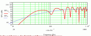
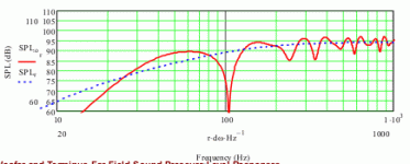
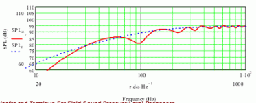
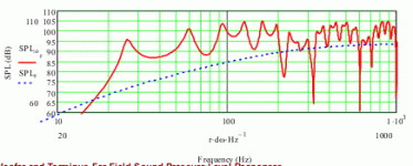
I modeled the FE167E BIB also using King's MathCad model and got the same ragged SPL response curve. I understand that these sound much better than they model but am concerned about how ragged it appeared. To "flatten" in the model I added stuffing with increasing densities. Here's 0.125 lbs/ft3:
Attachments
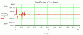
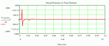
Stuffing does "flatten: the peaks and nulls but also rolls off the low end response - probably not a good trade off. It does however greatly improve the impulse response; some maybe it is a good trade off..?
Does anyone have experience with BIB's and stuffing?
Here's the impulse response lightly stuffed (0.125 lbs/ft3):
Does anyone have experience with BIB's and stuffing?
Here's the impulse response lightly stuffed (0.125 lbs/ft3):
Attachments
Yes. It's all on the thread, though you won't want to wade through all that.
The response you are geting looks the way it does because you're modelling a 1/2 space response. But the BIB is specifically intended for 1/8 space placement (corners). The vent is actually a terminus, not a horn mouth: the room itself completes the flare and forms the mouth. None of this is currently accounted for with Martin's worksheets. This is not me denigrating Martin's work; I'm one of his most vocal supporters, and he's a good friend of mine; I'm just pointing out the current limitation of the software with regard to modelling corner horns. FR, impedence and impulse response are all dramatically smoothed by the correct corner placement. This is why the BIB was ignored for a while; people forgot that this speaker actually uses the room as a continuation of the cabinet, and that they were only modelling part of the resultant system.
Stuffing the BIB is simple enough. The harmonics we want to clobber are best done with about 0.25lbs ft^3 in the point above the driver, some wadding behind the driver to to prevent reflections back through the cone, and a nice thick layer of damping on the cabinet base. That's about it.
The response you are geting looks the way it does because you're modelling a 1/2 space response. But the BIB is specifically intended for 1/8 space placement (corners). The vent is actually a terminus, not a horn mouth: the room itself completes the flare and forms the mouth. None of this is currently accounted for with Martin's worksheets. This is not me denigrating Martin's work; I'm one of his most vocal supporters, and he's a good friend of mine; I'm just pointing out the current limitation
Stuffing the BIB is simple enough. The harmonics we want to clobber are best done with about 0.25lbs ft^3 in the point above the driver, some wadding behind the driver to to prevent reflections back through the cone, and a nice thick layer of damping on the cabinet base. That's about it.
Agreed and disagreed in equal proportions. It's not LS3/5a monitor flat, but most horns aren't, and it's no worse than others if placed correctly. These traditional P.G.A.H. Voigt chamberless corner-horns operate over a very wide passband, but the ripple this would cause is negated by the room, providing the driver / cabinet are properly matched. Mass loading is a useful tweak, but transforms it into a QWR cabinet rather than a horn. A good move if the driver has characteristics that would render it unsuitable for this loading (e.g. too high a Q or Vas). Are you still running those iosphon (I think?) drivers in yours BTW? Last I recall, one had died. Hope you managed to get them going again -be a crying shame if they had to go off to that great scrap-heap in the sky.
I got replacements which I am running now, along with Isophon paper cone tweeters. Tried a few other designs but came back to the bigger is better because of its natural tight bass response.
My understanding is that any voight pipe type enclosure are only an approximation to a true horn enclosure, The pipe is only tuned to one frequency and its harmonics, frequencies between experience cancellation - hence the ragged response.
I personally found the mass loading cleaned up the bass considerably at the cost of reduced bass volume.
Simply the best cab availble without going to true horns. I'll have to take some photos and submit them to Godzilla's site - since mine date to before the current craze.
Shoog
Glad you got some replacements sorted out.
Depends what you call a Voigt pipe I suspect. In the case of the BIB, it's a positive taper, and the gain back-wave begins at 1/2 wavelength of the tuning frequency; which technically makes it a horn. With WxD ratios optimised (1:1.4142) you have a conical profile too. The throat CSA of 0 should provide maximum pipe-gain across as wide a passband as possible; the lack of chamber means no upper horn cut-off of course. Greg or Martin are the better people to go into the details though -you other there guys?
Out of interest, could you let me know your cab dimensions and the parameters of the drivers?
All the best
Scott
Won't a conical profile be generated in a BIB design regardless of the WxD being optimized? I understood that the conical part refers to how area is expanding.
----
Also - I voiced in the earlier posting about the ragged response of a BIB and Scottmoose kindly replied "The vent is actually a terminus, not a horn mouth: the room itself completes the flare and forms the mouth. " (Which I understand!) but... is it possible to check this by modelling a very long conical horn with a large mouth based on the length and terminous specified for a BIB? For example I looking at the BIB for an Fostex FE126E with a length of 97 in and terminous of 67 in2. Using the same expansion rate, at 190 inches the "mouth" would be approximately 24 Sd (~242 in2). Modelling this monster conical horn gives the result below.
Still very ragged but with surprisingly deep bass. The assumptions I'm making of course is that the expansion of the wave as it leaves the terminous stays conical (a big assumption) and that 190 in of theoretical horn is possible with a BIB thats 4 feet tall already with ceilings in my livingroom 9 feet tall (combined length of horn plus height to the ceiling is 157 in).
Is this a valid way to use King's models to investigate BIBs?
Incidently I have been following the forum for some time and cut the panels for a FE126E BIB today and have the drivers and stuffing waiting!
Attachments
Not at this time there isn't, unless you have a fair amount of experience with this type of enclosure; in which case you can use it for rough sizing. Martin is working on 1/8 space modelling, but don't hold your breath for a while -it'll be the new year at the earliest before the next round of upgrades will start to emerge.
No, the expansion rate in the cabinet will not be conical unless you ensure the WxD dimensions are carefully factored in.
The expansion does not stay conical however once it leaves the terminus. Depends upon placement & the room of course, etc., but you'll get a more or less abrupt flare for a start, causing a rapid decrease in pressure, & killing the peak you would nominally get at Fc. 1/8 space radiation actually will increase the theoretical size of the mouth by a factor of 8 (yup); which will also lift the resistive portion of the acoustic impedence by the same degree; and incidentally attenuating reflections back down the line, killing the nulls in the 1/2 space or anechoic response. So, unfortunately, trying to increase the line length in MathCad & following the same profile does not work. Incidentally, the huge length assumed here for a small, relatively high Fs driver will itself mess up the response because it's tuned way below the 0.707Fs safe threshold, so the midbass will vanish.
For small drivers, I actually prefer downward venting, with the cabinet lifted up somewhat, so it couples to the bottom, rather that the upper corner of the room -the cabinet for a small driver tends to be too short to couple to the room as effectively as taller cabinets do. They still work quite well, but it's a bit of a compromise. Alternatively, you can keep the upward venting type, and again, elevate it on a tall plinth or stand. A neat inverted type was done recently for the FE108ESigma by simply extending the front and side panels and leaving the rear open. These cabinets are not MLTL flat, but neither are they as bad as they look in a simulation.
Hope this helps & good luck with your new cabinets!
Scott
There was a big discussion about the properties of Quarter wave designs on the "Fullrange driver Forum". If I remember the conclusions correctly. Quarter Wave designs are a cross between a horn and transmission line and share attributes of both. A perfect transmission line is stuffed such that there is no back wave to speak of (or predominently the fundamental), this takes the nulls out of the equation. Since most quarter wave designs are lightly/zero stuffed the nulls come back into play. If the nulls are present at the terminus they will be present in the room regardless of room loading. Of course room loading may improve things to a greater or lesser extent.
Quarter Wave designs are not greatly respected over on the "fullrange Driver Forum" for exactly these reasons.This is why the whole idea of mass loading was developed in order to remove the nulls from the overall situation. My understanding is that the BIB design pushes these effects down to a low enough frequency to make them less objectionably and to some extend become lost in the overall cab-room interaction.
Nothing you can do will get rid of those nulls once they have been created, and intil you turn the BIB into a perfect conical horn-which it can never be, then you are stuck with the ragged response.
I will measure up the dimensions of my cabs, but unfortunately the drivers don't have any published specs.
Shoog
Yes, I'm also a member of the FR forum. I rarely use the term TL -never did like it, it's electrical, not acoustic. Bailey & Bradbury have much to answer for IMO, though to be fair, non-resonant lines can be useful in specific circumstances. Personally, I'd just build an aperiodic box and have done with it if that's the sort of response wanted, but to each their own!
Most QWRs have light stuffing, as you note; usually in the first portion of the line (dependant upon the specific design criteria) as the object is to damp out the harmonics while preserving the fundamental. As stuffing is at it's most effective where air velocity is highest, and the unwanted HF occurs closest to the sealed ennd, that's where it tends to be placed, with none, or little in the last portion to preserve the first mode resonance. The designs GM & I have done on the 'zilla pages assume no stuffing at all, with only suggested general locations because people can sort that out and refine it for themselves once they get them in-room & optimised to their own conditions. All horns, of course, being sealed at one end and open at the other, are QWRs; they don't have a choice in the matter.
Thning is, we're not just talking about room-gain here. In the case of these cabinets, the room actually forms a part of the resultant system; see my above post. Effectively, it's part of the cabinet, just like it is for, say, Ron's A126 horn, the Frugelhorn or the Buschorn, or any other corner horn you care to think of. The only real difference is that the BIB is much simpler, a little longer, and doesn't happen to have a chamber so it's passband is not limited. The 8-fold increase in accoustic impedence massively attenuates the apparant standing waves in the line when it's sized to suit a specific driver. While the response is not exactly monitor flat, in reality it's little worse than most BLHs out there, and better than some (like the duff Fostex FE166E cabinet). It's profile, if correctly dimensioned, is conical -not, perhaps, quite perfectly, due to the parallel sides, but it's hardly alone in that; 90% of horns share the same characteristic.
Some driver's don't suit the load, or are not ideal of course. High Q, high Vas drivers (like a lot of classic ones are -Goodmans, Philips etc.) are not a good match. A modern example; the one Greg & I did for the B200, is of gigantic proportions; Greg did an ML alternative (actually, he did it before a BIB version) which keeps the size just about managable, and provides a better response. In the case of those, high Q, high Vas drivers, the mildly ML approach is the superior, because the drivers are not suited to the cabinet. In most other cases, the non-ML types tend to have the edge.
Out of interest, which model drivers are you running? Are there no specs for them at all, not even Vas or Fs?
Regards
Scott
Scottmoose said:
Stuffing the BIB is simple enough. The harmonics we want to clobber are best done with about 0.25lbs ft^3 in the point above the driver, some wadding behind the driver to to prevent reflections back through the cone, and a nice thick layer of damping on the cabinet base. That's about it.
Scott: I have carpet underlayment in my garage and building BIB.
Can I use it on the cabinet base?, seem reasonable? or buy a dacron pillows?
thanks,
gychang
Scottmoose said:I'd use that as damping material behind the driver -it's perfect for that. You're better off with Dacron for the point and the layer on the base though.
got it, thanks.
gychang
Most QWRs have light stuffing, as you note; usually in the first portion of the line (dependant upon the specific design criteria) as the object is to damp out the harmonics while preserving the fundamental. As stuffing is at it's most effective where air velocity is highest, and the unwanted HF occurs closest to the sealed ennd, that's where it tends to be placed, with none, or little in the last portion to preserve the first mode resonance.
posted by Scottmoose
Finally had that "Eureka - I get it moment"! I modeled the BIB only with 0.75 lbs/ft3 of stuffing from the driver to the closed end and bingo MUCH better modeled response. So much so that I would suggest the Godzilla add a recommendation for stuffing there on the BIB pages at zillaspeak.com (perhaps in Lovechild's drawing on the "How to build a BIB" page?). In short - 'it keeps the best and reduces the worst'. (Incidently, with the stuffing in that area only, both the SPL response and impulse response modeled using King's MathCad model look similar to longer conical BLHs I've modeled).
- Status
- This old topic is closed. If you want to reopen this topic, contact a moderator using the "Report Post" button.
- Home
- Loudspeakers
- Full Range
- BIB with 167E, open top exposed
