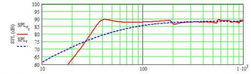
I'm finally getting around to moving my drivers from an early prototype/break-in box to something permanent. The attached result is from a Mathcad run for a 48" JX92s MLTL using MJK's older ported-box sheet. It also uses the manufacturers driver parameters. The results look very good, maybe too good. The main concern is the short port is moving problems beyond the high frequency limit of the sim, though I recall MJK once mentioned the sims aren't accurate beyond a few octaves above resonance anyway. Opinions from experienced eyes would be greatly appreciated.
Attachments
That cross-sectional area seems small to me.
Have you looked at Greg's MLTL designs from the Jordan website? Both the 31" and 48" lines have been built with good results.
http://www.ejjordan.co.uk/diy/
Have you looked at Greg's MLTL designs from the Jordan website? Both the 31" and 48" lines have been built with good results.
http://www.ejjordan.co.uk/diy/
Thanks Dumbass (that feels so wrong!) You might be thinking of the MLTL sheet, this sim was done with ported-box sheet. As I recall it's essentially identical with the added ability to alter port location. In the port-box version cross sectional area is expressed as the product of two values. A long winded way of saying, it's 8 x 8, not 8.8. The x-sectional area is actually much larger than the GM designs on Jordan's site.
Oops, my bad. Makes more sense now.rdf said:A long winded way of saying, it's 8 x 8, not 8.8.
Bob Brines said:
Greets!
Interesting the difference between the original WS Vs the latest one. Yours looks no less bazaar than rdf's done with it:
GM
Attachments
Thanks all. It probably would help to explain some of the reasoning behind those numbers. Regarding the low frequency point, the old sheets (you already know) don't model floor reinforcement. I felt it was safe to assume enough room gain to make up the dB or two. It helped to keep displacement a bit lower around 32 Hz, the common notion of where common source material ends. I also wanted a big baffle to lower baffle step as far as possible, at the expense of more difficult (and expensive) construction for low cabinet talk for sure.
Regarding the driver near-centre placement, through hundreds of runs it consistently yielded the smoothest port response above fundamental resonance. Compare the port output at ~100 Hz between the 48" and 36" lines to see what I targeted.
Regarding the driver near-centre placement, through hundreds of runs it consistently yielded the smoothest port response above fundamental resonance. Compare the port output at ~100 Hz between the 48" and 36" lines to see what I targeted.
GM said:Interesting the difference between the original WS Vs the latest one.
Ooops, I just caught the implication here. I was under the impression the basic physical models hadn't changed between the old sheets and the new. That's incorrect?
GM said:
Greets!
Interesting the difference between the original WS Vs the latest one. Yours looks no less bazaar than rdf's done with it:
GM
I wasn't talking about the final FR plot. The reason mine flattens out at the bottom is that I damped the port. Leave that port damping out and my model looks pretty much like yours. I was talking about the physical layout with the driver in the middle of the pipe and the port fully a foot up from the bottom.
Bob
- Status
- This old topic is closed. If you want to reopen this topic, contact a moderator using the "Report Post" button.
- Home
- Loudspeakers
- Full Range
- JX92S MLTL Alignment Sanity Check Request