I've been sorting through my notes that have been building up on the hard drive over the past 18 months or so and thought this might come in handy / be of interest for anyone out there. Nothing overly new of impressive, but someone might find it of some use, hense the post.
The Lowther Club of Norway 'Voigt Pipe' (Not that poor old P.G.A.H Voigt had anything to do with it). It's the entry for many people into the world of full-range DIY speaker-building -not sure why, probably because it looks dramatic and it's easy to construct.
Pity that, as it stands, it is, quite frankly, rotten. Below is the MathCad simulated response for this enclosure with the Fostex FE206E, which, rightly or wrongly, I suspect is the most popular driver that finds its way into these enclosures. (If you're interested, the response looks almost identical with the FE207E, FF225K, FE166E, FE167E and FF165K. With the Lowther PM6C drivers it was designed for, it looks even worse.)
But what if you've put a lot into your LCofN Voigt pipes, both in time and effort, and don't want to scrap them? Well, you're never going to have the best enclosure in the world I'm afraid. But I can suggest something that might help a bit: see next post.
Attachments
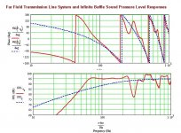
Still with me? OK, now if you ask anyone who is used to modelling quarter-wave enclosures with Martin's MathCad worksheets to pick one single thing they hate about the LCofN 'Voigt Pipe' above anything else, I would put money that it will be this:
They are an So=0 design. For those who haven't a clue what I'm on about at this point, So is the area of the top of the pipe. Now normally, when designing a Mass-Loaded TQWT enclosure, we say never use a top area less than the surface area of the drivers.
Thing is, in this case, that isn't the major problem. The drivers that frequently find their way into these things tend to be low Q designs. And they actually appear to be less affected than the higher Q drivers in this regard -in some ways, they seem to like the extra gain it provides. Gregreferred to this some time ago I believe?
What is a major issue is that although these things are mass-loaded (although I seriously doubt the thought even occured to the designer: he just set the vent area to the same surface area as the intended Lowther driver, or as close as he could get) -it's not enough.
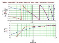
Here's the same enclosure, same driver, everything the same. But instead of the large vent, there's a 3" wide, by 3" long circular port, 4" up from the bottom. OK, it's not perfect by any stretch of the imagination, but it's a heck of a lot better than having big peaks and holes all over the place.
This works wonders for every driver I tried it out with. The lowest Q types need a bit of series resistance as you can see: I'd say 2ohms or so, to bring the response down, as it rises a bit. Ripple is mostly flattened, and on average, you suddenly get an extra 20Hz of bass. These assume 0.25lbs ft^3 of stuffing from the top to just below the driver by the way.
Oh yes -a BSC filter would be of use too, in-room. I'd try the one from Martin King's Project 2 MLTQWT which should do the job fine.
Hope some of this is of use. I figured I'd put it up here before I delted it all.
Best
Scott
They are an So=0 design. For those who haven't a clue what I'm on about at this point, So is the area of the top of the pipe. Now normally, when designing a Mass-Loaded TQWT enclosure, we say never use a top area less than the surface area of the drivers.
Thing is, in this case, that isn't the major problem. The drivers that frequently find their way into these things tend to be low Q designs. And they actually appear to be less affected than the higher Q drivers in this regard -in some ways, they seem to like the extra gain it provides. Gregreferred to this some time ago I believe?
What is a major issue is that although these things are mass-loaded (although I seriously doubt the thought even occured to the designer: he just set the vent area to the same surface area as the intended Lowther driver, or as close as he could get) -it's not enough.
Here's the same enclosure, same driver, everything the same. But instead of the large vent, there's a 3" wide, by 3" long circular port, 4" up from the bottom. OK, it's not perfect by any stretch of the imagination, but it's a heck of a lot better than having big peaks and holes all over the place.
This works wonders for every driver I tried it out with. The lowest Q types need a bit of series resistance as you can see: I'd say 2ohms or so, to bring the response down, as it rises a bit. Ripple is mostly flattened, and on average, you suddenly get an extra 20Hz of bass. These assume 0.25lbs ft^3 of stuffing from the top to just below the driver by the way.
Oh yes -a BSC filter would be of use too, in-room. I'd try the one from Martin King's Project 2 MLTQWT which should do the job fine.
Hope some of this is of use. I figured I'd put it up here before I delted it all.
Best
Scott
Attachments
Konnichiwa,
I'd note a few things about the LCONVP.
1) LF extension is limited, but at high efficiency, basically that thing is 95db/W/m down to 70Hz, not bad.
2) The first really nasty mode is at 300Hz, where a simple counter resonator or even likely just the right kind of stuffing could limit the "big dip" and likely flatten out the feever curve higher up.
3) Given the kind of FR evidenced by the FE206 toeing these in strongly or pointing them straight on so that the listener is off axis would probably give a quite even tonal balance.
So, with a little luck in stuffing and listening off axis the LCONVP could make a surprisingly decent speaker..
For the modified design we see that efficiency is traded for bandwidth, by reducing the resonant behaviour of line, the result is a rather early but shallow LF rolloff, which despite having a lower -6db point (~40Hz) than the LCONVP (~55Hz) would likely sound rather strident and forward with lean tonality, unless the speakers midrange is pulled down by around 5db to bring it in line with the LF.
I suspect persnally I would probably prefer a reasonably sorted version of the original to the "fixed" one.....
Sayonara
You're welcome guys -hope it's of use to someone. Note: I do not recommend constructing this cabinet. If you wish to build a TQWT for your driver; do yourself a favour and design a decent one, from scratch, in Martin's MathCad worksheets. It will reap major rewards. This mass-loading is just a boot-strap, quick fix for people who've already constructed the wretched thing and discovered the frequency response is all over the shop, and bass is serverely lacking.
Kuei -You make some very fair points. I agree with you regarding the toe-in, or listening off-axis. This would likely mitigate against requring series resistance; though I'd still advise using 24AWG or 30AWG wire with a low-damping factor amplifier, and a resistor with a high damping-factor amp or eveything under 120Hz or so is going to vanish.
Good luck if you think you're going to sort out the massive response issues this cabinet has via stuffing however. No chance. Promise. Stuffing exists only to damp harmonics that cannot be otherwise engineered out of a cabinet. There is a 20db hole in the response and that's just the one at 285Hz or so: you won't loose that by shoving more stuffing into the pipe, and for the love of heaven don't believe the myth that all additional stuffing does is clobber the efficiency. It will start to absorb the Fundamental, which is the whole reason for using a QWR in the first place. The mid-Q drivers like the FE207E and FE167E don't have this rise. Me, I'd rather have a flatter response than 20db holes and savage comb-filtering.
Be aware that whatever you do, this cabinet needs baffle-step correction. Active or passive, take your pick. Without it, you're going to run into even more problems. Passive will need a 2mH inductor with 4ohm resistor, approximate (minimum) values.
Best
Scott
How come those Cain's Abby's got so fancy reviews?
If you look at my Project #2, you will find the design details behind this type of ML TQWT enclosure. My earlier design has a strong ressemblance to the Abby. I would assume the performances of both are very similar.
Konnichiwa,
The port appears the depth of the front wall and appears to have a width nearly of the whole pipe and sign ificant hight. Looks more like a cosmetic cahnge than an acoustic one....
Sayonara
steenoe said:Except for the port, being made like Scott suggests
The port appears the depth of the front wall and appears to have a width nearly of the whole pipe and sign ificant hight. Looks more like a cosmetic cahnge than an acoustic one....
Sayonara
Thanks a lot for responding, MJK. Just visited your homepage and realised that I have some reading to do I see what you mean, your project 2, looks a lot like like the Abby's. Just shaped a little different. Come to think of it, I guess I could pop my Coral Flat 6-II into those boxes? They shouldnt be too different from those Fostex, should they? Sorry if this is a stupid question, but I really dont know that much about speaker-units
Steen
Kuei... Crossposting I love that
I see what you mean, your project 2, looks a lot like like the Abby's. Just shaped a little different. Come to think of it, I guess I could pop my Coral Flat 6-II into those boxes? They shouldnt be too different from those Fostex, should they? Sorry if this is a stupid question, but I really dont know that much about speaker-unitsSteen
Kuei... Crossposting
I love that
So you mean that fancy looking venthole in the Abby's are more or less a cosmetic showoff? Well, being in the process of planning a pair of speakers for my Pass F2 clone, I sure would like to get this just right from the start!! Could the venthole be just circular as in MJK's lovely box?? With the correct diameter, ofcourseLooks more like a cosmetic cahnge than an acoustic one....
I gather Terry chose the port shape for fluid air motion or something of the kind which I confess I haven't a clue about. Personally, I doubt there's any difference between that and a circular port, and indeed, I seem to recall Terry saying something to that effect. But his speakers are a real craftsmans product and designed to look good as well as sound good, which is fair enough. That's not to say I don't think Martin's Project 2 ML TQWT doesn't look good: I do. In fact, I like it as much as the Abby. Mine are in a nice, rippled sycamore veneer if you're interested, with 4 coats of lemon oil rubbed in (took forever -I'm the world's worst veneerer!)
I remember Terry stating on Bob Brines forum that it is not an So=0 design, despite external appearences. OK, this is a place for conjecture... Looking at the external dimensions, I'm going to take a stab here about the approximate internals of Abby. It's 68" tall externally, and comes to an external point at the top. So my guess is that it actually has an internal line length of about 60", or perhaps just a touch more, which probably means the So is around 0.7Sd, give or take. With external dimensions of, I believe 9" x 9" at the base, I'd reckon on an Sm of 3Sd or thereabouts. The driver position looks a bit high, but Terry knows what he's doing -Nelson (Pass) has some frequency response measurements of Abby that don't look too shaby. Martin's cabinets easily match them in this though, and completely stuff them in the bass (they go a good 15Hz lower), though they are less efficient. I've built 3 pairs of them so far, which says it all.
Best
Scott
I better stick to those then. The only thing I am sure of, after reading all this, is that I do not know enough about the subjectI've built 3 pairs of them so far, which says it all.
Well, I better stick to a ready made cookbook project Thanks a lot guys for your replies
Steen
You won't go wrong with Martin's Project 2 speakers. They are the most versatile enclosure I know of. Period. Best the with Fostex FE167E (the replacement for the FE164 he originally used, which was discontinued). Do let s know if we can help out, it's what we're here for!
You mention some Coral drivers. I can't speak for their quality, but if you have their T/S parameters or can give me a link to a site that has them, I'd be happy to run a MathCad sim on them in this enclosre and find out what modifications would be needed to the original design for you.
Best
Scott
You mention some Coral drivers. I can't speak for their quality, but if you have their T/S parameters or can give me a link to a site that has them, I'd be happy to run a MathCad sim on them in this enclosre and find out what modifications would be needed to the original design for you.
Best
Scott
Scottmoose:
<<You mention some Coral drivers. I can't speak for their quality, but if you have their T/S parameters or can give me a link to a site that has them, I'd be happy to run a MathCad sim on them in this enclosre and find out what modifications would be needed to the original design for you.
>>
I'm glad I stumbled across this thread -- because like, Steenoe, I have a pair of Coral Flat 6's that I was thinking of putting into a TQWP. And, like Steenoe, I've been wading thru' masses of material and websites (including Martin's), and am confused about whether I can pull it off. Anyway, the person who sold me the drivers had his (a different pair) measured as:
T/S Parameter Coral Flat 6B
Fo 68Hz
Qms 5.671
Qes 0.433
Qts 0.402
Vas 31.346 L
The Coral Audio brochure lists the following specifications, which are somewhat different from the above (Qo of 0.52 and Fo of 45 Hz).
Nominal size: 6.5 in.
Impedance: 8 ohm
Min. resonance frequency (Fo): 45 Hz
Power input: 10 W
Sensitivity: 98 dB
Frequency response: 45 ~ 20,000 Hz
Magnetic flux density: 11,000 Gauss
Qo: 0.52 (45 Hz)
Equivalent mass: 0.23 oz
Diameter: 8 in.
Depth: 2-9/10 in.
Dimension of baffle opening: 5-3/5 in. (7 in.)
Mounting hole dimension: 6-1/10 in. (7-2/5 in.)
Magnet weight: 14 oz.
Total weight: 3 lbs.1 oz.
The bass-reflex cabinet they suggest:
Dimensions: 10-4/5 (W), 20.5 in. (H), 7-2/3 in. (D)
The driver is mounted in a 7-in-dia baffle opening located 5-9/10 in. from the top. The port is located 4 in. from the bottom, and is a square of 2-3/5 x 2-3/5 in., and 4-in long.
The Coral's I have (apparently) been unused, but their vintage status (~20 years old) may account for the discrepancies.
The Frequency Response curve in the Coral brochure shows a gradual LF rolloff from about 150 Hz. They also have a broad, shallow dip between 1,000-1,500 Hz (about -7 dB, or so), and dip a little raggedly (-5 db) between 3,500 - 5,000 Hz, and finally rolloff very gradually above 10,000 Hz. The Freq-Response curve that was scanned in the brochure is of such low resolution that I'm making some big guesses here.
I've tried simulating in Martin's Mathcad program, but given that I am fairly clueless (this is my first post!!), I know I'm doing most things wrong.
Scottmoose, I'd appreciate it if if you could run these through your simulations, and let me know the results, and how to proceed, then I may be able to duplicate your results myself on Mathcad and start learning how to use it.
Thanks a lot in advance,
Talanat
Thanks a lot Scott, most kind of youDo let s know if we can help out, it's what we're here for!
I am glad you did, tooI'm glad I stumbled across this thread
You have more parameters than I was able to find. Talatnat, are yours Flat6's the "II" version?
Many people says that the Corals sound better than the Fostex's.
But I wouldnt know, since I never compared them. Nonetheless, I think the Corals has a very good reputation. I posted some questions about mine some time ago, here you can see the drivers: http://www.diyaudio.com/forums/showthread.php?s=&threadid=59879&highlight= I tried them in the recommended bassreflex box and they sound pretty good, indeed. Take a look here: http://www.diyaudio.com/forums/showthread.php?postid=797590#post797590
I will post the parameters I have if they differ from talatnat's.
This thread is getting pretty interesting, indeed
Thanks Scott
Steen
Right, this is what I've come up with for the Coral Flat 6II.
First up, I'll say I've had to fudge some of the data as I can't find the full T/S parameters. However, the most important: Vas, Qe/m/t are a start. I calculated the Bl factor using Martin's check-sheet as 9.771; the rest aren't quite so important, so we should be at the very least in the ball-park here.
Enclosure is 42" tall, 9" wide, 10" deep (internal). The driver is set 11.25" from the internal top, the port is 4" x 2" (WxD) and set 3" from the internal base on the front baffle.
2ohms of series resistance were applied: you can do away with that if you can cope with the slightly rising response or your room is bass-heavy. Just use a run of high-resistance wire: a single pair of 24AWG extracted from a length of Cat5 would be ideal, or a run of 24AWG magnet wire.
0.35lbs ft^3 of stuffing. Stuff from the top down to just below the driver. Predicted frequency response is shown below.
They'll need a BSC circuit, like most enclosures do. Try a 2mH inductor with a 4-8ohm resistor.
All dimensions were made in the latest (as yet unreleased) version of Martin King's Ported Box worksheet. You can do the same with the existing sheet, though adding the series resistance is a bit trickier. This isn't actually a reflex enclosure, but an MLTL. I don't think these drivers will work too well in an ML TQWT, I'm afraid.
Best
Scott
Attachments
Thanks Scott!!
Those curves look pretty good! Tks again...
Steen: The Coral's I have are Flat 6B, 15 W, 8 ohm (these are what's printed on the back -- and the speakers don't have the sticker specifying the model that yours do). I haven't seen the B's mentioned too much, and don't have any specs on them. The manufacturer's numbers I posted are for just Flat 6 (no suffix) and the only thing I can make out is that it differs in the input power, which is given as 10 W, 96 dB; I also have Coral's Flat 6 II specs listed as as 30 W, 92 dB. So, maybe these reflect some continuum series of power ratings/sensitivity.
The measured T/S numbers I posted were for Flat 6 Bs.
Nice F-2 clone!
Now, to get to work figuring out Scott's numbers...
Scottmoose said:Right, this is what I've come up with for the Coral Flat 6II.
First up, I'll say I've had to fudge some of the data as I can't find the full T/S parameters. However, the most important: Vas, Qe/m/t are a start. I calculated the Bl factor using Martin's check-sheet as 9.771; the rest aren't quite so important, so we should be at the very least in the ball-park here.
Enclosure is 42" tall, 9" wide, 10" deep (internal). The driver is set 11.25" from the internal top, the port is 4" x 2" (WxD) and set 3" from the internal base on the front baffle.
2ohms of series resistance were applied......
All dimensions were made in the latest (as yet unreleased) version of Martin King's Ported Box worksheet.
I don't think these drivers will work too well in an ML TQWT, I'm afraid.
Greets!
Well, I don't have the same PORTED WS, but FWIW, using these specs in your pipe I get a very rolled off response below ~100 Hz:
Fs = 68 Hz
Re = 8 ohms
Lvc = 0
BL = 9.46 NA (calc'd)
Sd = 214.0834 cm^2 (6.5" nom.)
Rs = 2 ohms
Vas = 31.346 L
Qed = 0.433
Qmd = 5.671
Qtd = 0.494 (auto calc includes Rs)
To get something with as much LF gain as yours I had to use a large, fast taper ML-TQWT:
L = 72"
zdriver = 36"
zport = 69"
SO = 9"^2
SL = 180"^2
rp = 2.75"
Lp = 0.75"
GM
Well, I'm blowed if I can figure that one out Greg! Thanks for the warning. I've just plugged the specs back into the sheet, this time using the ones you calculated and posted above as you've more experience at figuring out T/S parameters from older drivers than me. But the predicted response has come out practically the same, with only minor changes due to the slightly different driver parameters entered. So I've honestly no idea what's going on there. Do you have a set of response curves you could post? Perhaps we could then send them off to Martin for comparison: as I'm using the new sheet this might indicate there's a bug in there somewhere. I'll have a go in one of his existing sheets and see what happens in that too. Very odd. I'll get back in a few minutes. Oh yes -I had a look at your ML TQWT too; looks good to me! I tend to get hung up on only going to a 2" radius maximum for the port, which is obviously limiting the options a bit! Something I need to be more careful about doing as it clearly rules some possibilities out, many thanks as usual.
Best
Scott
Best
Scott
Very interesting indeed. They don't match. Rather than using the current Ported Box sheet, I tried it in the ML TQWT sheet. This is what it suggests for the Coral driver (GM's calculated parameters) and the MLTL enclosure without any series resistance.
Doesn't look so good here. But it doesn't look too bad either -I've seen a whole lot worse, and as a theoretical exercise, there doesn't appear to be much that couldn't be sorted by juggling some port dimensions and adding the 2ohms series reistance we both went for to get it flat. Strange -any thoughts?
Best
Scott
Attachments
- Status
- This old topic is closed. If you want to reopen this topic, contact a moderator using the "Report Post" button.
- Home
- Loudspeakers
- Full Range
- L C of Norway Voigt Pipe -quick fix