Hi all!
After reading this forum for a while, I finally decided to get a set of W4-1320's. They arrived last week, and I just took some measurements using the Woofer tester...
I now have all data, but must take a decision. I can either build 4 mini-monitors with BSC, or a pair of monitors with 2 drivers each.
But I still haven't decided. Should I build the monitores with the 2 drivers in a bipolar configuration, or a front firing one?
I initially thought about bipolar so as to avoid BSC altogether. I did an MLS measurement, and found that there's a small break-up node at around 5 KHz, but nothing higher up. If this is correct, I could get away with a crossoverless speaker if I build it in a bipolar configuration... but I've seen an Omega Loudpspeaker using T-B drivers with both units firing forward (I assume using a lot of BSC and notch filtering).
Is there any real advantage in going for a front firing configuration? Do full-range bipolar loudspeakers sound great? Will I lose too much efficiency by going bipolar? Is there a general consensus on this?
If you need 4 speakers go ahead and build them.I now have all data, but must take a decision. I can either build 4 mini-monitors with BSC, or a pair of monitors with 2 drivers each.
Otherwise I´d vote for a bipolar.
Look here:
http://www.quarter-wave.com/
You´ll find the matchcad explorer and simulation sheets to build a TL.
You just have to "adjust" the input values when you parallel the drivers.
100% agreed. Just to add; remember, when you parallel drivers, Vas doubles, Sd doubles and impedence halves. Everything else remains the same.
Bipolar MLTL or ML TQWT every time. Once you've heard bipolar speakers, which have many of the advantages of dipolar types, it'll be a struggle to go back to many more conventional box speakers. Make sure you physically couple the magnets of the drivers together to get even more advantage -a length of dowel rod will do. That way, in full bipolar push-push mode, you'll practically neutralise cabinet vibrations.
Best
Scott
Thanks a lot for your suggestions!
Bipolar it will be. I've been wanting to try to build one, since I'd love not to lose efficiency by using a BSC circuit (the last speakers I built needed far too much compensation, and they sound a bit dead, IMHO).
TQWT? MLTL? Great, I have a lot to learn!") I assume you mean Quarter Wave Transmission Line, and Medium Length Transmission Line. I hope I'm right. I was thinking about doing a vented box, but I really think I'd love the TL bass.
I assume you mean Quarter Wave Transmission Line, and Medium Length Transmission Line. I hope I'm right. I was thinking about doing a vented box, but I really think I'd love the TL bass.
My only bipolar speakers were a pair of Definitive Technology BP-8's, and I seriously doubt they were real TL. I think they were vented speakers that were tuned very low...
After testing the Bamboo drivers, though, I think I have a shot at building some very nice speakers for a decent price.
I assume a tall, narrow column would be a good idea. I need to take a look at the sites you mentioned, and study, study, study!
Thanks again. I really appreciate it!
Bipolar it will be. I've been wanting to try to build one, since I'd love not to lose efficiency by using a BSC circuit (the last speakers I built needed far too much compensation, and they sound a bit dead, IMHO).
TQWT? MLTL? Great, I have a lot to learn!
I assume you mean Quarter Wave Transmission Line, and Medium Length Transmission Line. I hope I'm right. I was thinking about doing a vented box, but I really think I'd love the TL bass.My only bipolar speakers were a pair of Definitive Technology BP-8's, and I seriously doubt they were real TL. I think they were vented speakers that were tuned very low...
After testing the Bamboo drivers, though, I think I have a shot at building some very nice speakers for a decent price.
I assume a tall, narrow column would be a good idea. I need to take a look at the sites you mentioned, and study, study, study!
Thanks again. I really appreciate it!
ML TQWT is a Mass Loaded Tapered Quarter Wave Tube. An MLTL is a Mass Loaded Transmission Line.
TQWT reverses the traditional TL taper: it starts narrow at the top, or closed end, and has an opening at the wide end.
An MLTL is a little different. It can be either a regular, wide at closed end, opening at narrow end TL, or it can be a straight, untapered TL, with no folds, and of equal area at the sealed and open ends.
The Mass Loading part is the cunning bit. Rather than just leaving the open end, err, open, as was usual with traditional TL speaker designs, it's actually mostly closed, apart from a vent or port, of a size you determine. The air mass in the constricted area of the port port provides an additional load on the quarter-waves the speaker cabinet is designed to generate, and often enables it to go lower, smoother. Remember, TL is an electrical, not an acoustic term. The correct phrase is Quarter Wave Resonator.
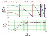
One of the things I love about Martin King's Project 2 ML TQWT (see here for the basic shape and idea: http://www.quarter-wave.com/Project02/Project02.html ) is the basic cabinet geometry is so versatile. So here's something to whet your apetite: Below, you'll see a MathCad generated response curve for your drivers in the following cabinet.
So=Sd (the combined surface area of your two drivers. So is the top by the way)
Sm=7Sd (7 times the combined surface area of your two drivers. Sm is the larger, bottom end).
Cabinet height is 60"
Drivers mounted in bipolar push-push configuration at half the line-length. Couple the magnets together with dowel to maximise the benefits of the configuration.
There's a 3" diameter, 1" long port centred 3" up from the base. Use 0.25 lbs to the cubic foot of stuffing, and stuff from the top to just below the two drivers. And that's it. Easy, isn't it.
On a practical level, you can reduce that ripple in the response by increasing the stuffing, but that will damage the fundamental, and I doubt it would be audible anyway. Remember to mentally add 6 db to the levels indictated in the curve to account for the two drivers being parallel wired (the current MathCad worksheets don't do this automatically). BSC isn't an issue as you'd going bipolar, which solves this at a stroke.
You might feel this is a big cabinet, when you see Martin's original -well, it's not small, but the width and depth will all be about 1/3 smaller in your case, due to the smaller surface area of the combined two 4" Tang Band drivers compared to the larger single Fostex unit Martin used. And besides, it looks elegant, doesn't it!
Cheers for now
Scott
TQWT reverses the traditional TL taper: it starts narrow at the top, or closed end, and has an opening at the wide end.
An MLTL is a little different. It can be either a regular, wide at closed end, opening at narrow end TL, or it can be a straight, untapered TL, with no folds, and of equal area at the sealed and open ends.
The Mass Loading part is the cunning bit. Rather than just leaving the open end, err, open, as was usual with traditional TL speaker designs, it's actually mostly closed, apart from a vent or port, of a size you determine. The air mass in the constricted area of the port port provides an additional load on the quarter-waves the speaker cabinet is designed to generate, and often enables it to go lower, smoother. Remember, TL is an electrical, not an acoustic term. The correct phrase is Quarter Wave Resonator.
One of the things I love about Martin King's Project 2 ML TQWT (see here for the basic shape and idea: http://www.quarter-wave.com/Project02/Project02.html ) is the basic cabinet geometry is so versatile. So here's something to whet your apetite: Below, you'll see a MathCad generated response curve for your drivers in the following cabinet.
So=Sd (the combined surface area of your two drivers. So is the top by the way)
Sm=7Sd (7 times the combined surface area of your two drivers. Sm is the larger, bottom end).
Cabinet height is 60"
Drivers mounted in bipolar push-push configuration at half the line-length. Couple the magnets together with dowel to maximise the benefits of the configuration.
There's a 3" diameter, 1" long port centred 3" up from the base. Use 0.25 lbs to the cubic foot of stuffing, and stuff from the top to just below the two drivers. And that's it. Easy, isn't it.
On a practical level, you can reduce that ripple in the response by increasing the stuffing, but that will damage the fundamental, and I doubt it would be audible anyway. Remember to mentally add 6 db to the levels indictated in the curve to account for the two drivers being parallel wired (the current MathCad worksheets don't do this automatically). BSC isn't an issue as you'd going bipolar, which solves this at a stroke.
You might feel this is a big cabinet, when you see Martin's original -well, it's not small, but the width and depth will all be about 1/3 smaller in your case, due to the smaller surface area of the combined two 4" Tang Band drivers compared to the larger single Fostex unit Martin used. And besides, it looks elegant, doesn't it!
Cheers for now
Scott
Attachments
Scott, I can't thank you enough for your information. I've been reading as much as I can about the terms and types of loading you posted about, and I think I've been learning quite a bit I was going to build a traditional bass reflex box, but maybe I should take my time and understand QW a bit more. From what I can understand, they can go lower than either BR or sealed boxes, and have a lower group delay (I like that a lot).
I have a couple of questions about the cabinet design you told me about, though. I understand the 60" height, the drivers mounted at 30" height, and the 3" port at the bottom of the cabinet. But, how deep should I build the cabinet? Also, the what does Sm represent? Sorry about such basic questions.. I guess I still have a bit to learn.
Once again... thanks. Your help is very appreciated!
I was going to build a traditional bass reflex box, but maybe I should take my time and understand QW a bit more. From what I can understand, they can go lower than either BR or sealed boxes, and have a lower group delay (I like that a lot).I have a couple of questions about the cabinet design you told me about, though. I understand the 60" height, the drivers mounted at 30" height, and the 3" port at the bottom of the cabinet. But, how deep should I build the cabinet? Also, the what does Sm represent? Sorry about such basic questions.. I guess I still have a bit to learn.
Once again... thanks. Your help is very appreciated!
fjhuerta said:I have a couple of questions about the cabinet design you told me about, though. I understand the 60" height, the drivers mounted at 30" height, and the 3" port at the bottom of the cabinet. But, how deep should I build the cabinet? Also, the what does Sm represent? Sorry about such basic questions.. I guess I still have a bit to learn.
Once again... thanks. Your help is very appreciated!
'So', 'Sm' are the cross-sectional areas of the cabinet. 'So' at the top of the cabinet 'Sm' is the cross-section at the cabinet. I believe Scott recomended 114cm^2 at the top of the cabinet and 798cm^2 at the bottom of the cabinet. So the depth depends on the width of the cabinet, and in which direction the cabinet expands as it gets closer to the floor.
Hope all that makes sense. Good stuff to learn. In the mean time you could put the tang-bands in a 4liter sealed enclosure. Should be nice and the tang-band has plenty of x-max for moderate listening.
Joe
Try these internal dimensions; you can adjust and modify to you heart's content, so long as the surface area of the two remains unaltered. Remember, Sd = the combined surface area of the two drivers, which is approx 114cm^2. For the following, I decided to stick with the original 10" cabinet depth Martin used for his Project 2 ML TQWT.
So (the area of the narrow top) = Sd. Go for 1 3/4" wide x 10" deep.
Overall cabinet height: 60".
Drivers positioned 30" from the base, back to back, on the front and rear baffles, preferably with their magnets coupled together witha length of dowel rod.
Sm (the area of the wide bottom) = 7Sd. 12 1/4" wide x 10" deep.
3" W x 1" D port on the front panel with its centre 3" up from the base.
This will give a tall, elegant cabinet of reasonable proportions domestically speaking, especially if you veneer / finish them nicely, that is quite cheap, and very straightforward to build. A TL will generally go lower than a BR box, but it also tends to have a much purer midrange as the stuffing eats the rear wave very well. This is the cabinet I'd be building if I had four of those drivers anyway.
Cheers for now & goold luck with whatever project you decide upon
Scott
Scottmoose said:Just to add; remember, when you parallel drivers, Vas doubles, Sd doubles and impedence halves. Everything else remains the same.
Greets!
While impedance halves, we have to halve Re, Le for the program to properly plot it.
Scottmoose said:So=Sd (the combined surface area of your two drivers. So is the top by the way)
Sm=7Sd (7 times the combined surface area of your two drivers. Sm is the larger, bottom end).
Cabinet height is 60"
Drivers mounted in bipolar push-push configuration at half the line-length. Couple the magnets together with dowel to maximise the benefits of the configuration.
There's a 3" diameter, 1" long port centred 3" up from the base. Use 0.25 lbs to the cubic foot of stuffing, and stuff from the top to just below the two drivers.
Remember to mentally add 6 db to the levels indictated in the curve to account for the two drivers being parallel wired (the current MathCad worksheets don't do this automatically). BSC isn't an issue as you'd going bipolar, which solves this at a stroke.
Hmm, using the PORTED WS/TB's published specs I get a bit wider BW dip and somewhat more peaking at Fb than you, but the big difference is I had to use 2.25 ohms series R to get the same IB/simmed response, so it seems kind of misleading to me.......... Also, once the 2.25 ohms is removed, the correct +6 dB is plotted, so no need to do any mental visualizations beyond how the room's acoustics is going to muck it up.
GM
Ouch! Thanks for letting me know. I've just looked back at the saved file, and I can see -guess what I forgot to do? -yep, halve the impedance. I must be getting old or something. I hold my hands up on that, and humbly apologise for any problems caused by my incompetence.
On the up side though, even as it stands, I've seen worse, and with the 2.25ohms series resistance you specified, it looks quite respectable. Perhaps a run of 24AWG would negate the requirement for the series resistor? I recall Bob Brines changing to this with his FT1600MK2 I believe, which allowed him to junk the extra component, as I understand it.
Cheers
Scott
Scottmoose said:......I've seen worse, and with the 2.25ohms series resistance you specified, it looks quite respectable. Perhaps a run of 24AWG would negate the requirement for the series resistor?
Greets!
Agreed. Right, using magnet wire or similar of the requisite gauge to get the desired voltage drop is technically superior to adding a resistor, though with wide BW drivers or compression loaded horns, the 'sound' of PIO caps is not to be summarily dismissed.
For sure the wire is the most bang/buck choice though.GM
- Status
- This old topic is closed. If you want to reopen this topic, contact a moderator using the "Report Post" button.
- Home
- Loudspeakers
- Full Range
- Got 4 W4-1320 T-B Bamboo Drivers... need some ideas!