A lucky break!
While waiting to build one of the more popular boxes for the Alpair 7.3, I stuck it into a BIB that I had built for the fostex fe126 many years ago and had abandoned. What luck! In the 6 months or so I have had them they have blossomed into a delightful set of speakers.
One of the problems I had earlier with the fe126 was that I had to stuff it lightly to get any decent bass out of it. Which also resulted in quite a bit of the mid frequencies coming out of the mouth killing all imaging and soundstage. Because of the Alpair's built in baffle step I am able to stuff it well and still get great bass.
So if any of you have this BIB and are in the mood for some speaker rolling, try this and you wont be disappointed. Just remember that the Alpair's require a gradual and gentle break in. So give it a month or two. Also despite its specs it is a very efficient speaker. I am driving it with an SE2A3(3-4 watts).
Can a "Flat" BIB work?
I was wondering if the BIB can be "squashed" flat, preserving the cross sectional area but making the aspect ratio a flat box with the driver mounted on the flat side so that the BIB can be mounted on a wall like a painting? For example, the driver I intend to use will produce a BIB with cross sectional area of about 48 sq inches based on 6 in wide x 8 in deep. Can I make this 4 in wide by 12 in deep (with driver on the long side)? I would imagine that it might change the "character" of the BIB sound. Nonetheless, I am thinking of trying it out quickly in foam core.
I was wondering if the BIB can be "squashed" flat, preserving the cross sectional area but making the aspect ratio a flat box with the driver mounted on the flat side so that the BIB can be mounted on a wall like a painting? For example, the driver I intend to use will produce a BIB with cross sectional area of about 48 sq inches based on 6 in wide x 8 in deep. Can I make this 4 in wide by 12 in deep (with driver on the long side)? I would imagine that it might change the "character" of the BIB sound. Nonetheless, I am thinking of trying it out quickly in foam core.
Last edited:
Yes, though the divider board will need to be offset between the sides to ensure it doesn't create a choke point, ergo maybe longer or shorter, but don't know of a rule-of-thumb or easy math to calculate it, so a bit of scale modeling/folding with heavy paper is what I do.
GM
GM
You could straighten the BiB out to get the mouth closer to the ceiling if the specs permit. Otherwise you will probably have to split the divider board into a v shape (seen from the front) or alternatively shift the driver to one side.
The usual configuration will not work with a very squashed BiB, since the hornloading will be minimal and closer to parabolical. You'll end up with with a transmisson line instead of a horn.
The usual configuration will not work with a very squashed BiB, since the hornloading will be minimal and closer to parabolical. You'll end up with with a transmisson line instead of a horn.
Last edited:
I was wondering if the BIB can be "squashed" flat, preserving the cross sectional area but making the aspect ratio a flat box with the driver mounted on the flat side so that the BIB can be mounted on a wall like a painting? For example, the driver I intend to use will produce a BIB with cross sectional area of about 48 sq inches based on 6 in wide x 8 in deep. Can I make this 4 in wide by 12 in deep (with driver on the long side)? I would imagine that it might change the "character" of the BIB sound. Nonetheless, I am thinking of trying it out quickly in foam core.
Must be reading my mind. I was staring at the wall last night thinking this exact thought. Time was not permitting me to start my Cornu project. However, as I was looking through a notebook, I found plans that were drawn up to try to build a BIB into a wall. Basically it was a BIB with the driver moved to the side.
So enough rambling, what I imagined was a wall mounted BIB that had the paths split so one would fire up and the other down. This may or may not work. Was going to try to draw it up later. The big issue I saw was the size of the units. Most BIBs are large. A box that is quarter length may work better than the half wave monster.
Is this a bad idea in anyone's mind?
Hello one and all... I've been reading steadily for the last month and am at page 311 and going strong. I have decided to build a set of BIBs. I have a set of Fostex FE206en breaking in as we speak and have sourced some 100 year old barn lumber (spruce) for the front of the speakers.
1 inch thick, once sanded and finished, it should have a nice patina I would think.
I'm Going to build the sides out of 1inch plywood and the slant bottom and rear out of presswood or particleboard. (In this case it will mean I can buy one sheet of one inch plywood and one of half inch particleboard (which the pieces will be doubled up and glued together)
The dimensions from the excel Bib calculator give me 10*13*87inches w*d*h
Are these still accurate or have more recent builds pointed towards different dimensions?
I haven't decided what to do with the supra-baffle as of yet. I might make one a la frugalhorn or see if I can turn something on a lathe.
My two main concerns are:
Do my dimensions sound correct?
And is the use of particleboard optimal for the slant, bottom and back?
(I've read differing opinions as to if the back should or not be built with particleboard)
Thank you,
-andre-
Yes, though the divider board will need to be offset between the sides to ensure it doesn't create a choke point, ergo maybe longer or shorter, but don't know of a rule-of-thumb or easy math to calculate it, so a bit of scale modeling/folding with heavy paper is what I do.
GM
I was thinking of slightly curving the divider to bow concave on driver side to make room, and bow convex on horn mouth side which makes it kind of exponential horn. Easy to curve with foam core. How does this affect tuning? Do I need to run sim in Hornresp or just go for it?

The dimensions from the excel Bib calculator give me 10*13*87inches w*d*h
My two main concerns are:
Do my dimensions sound correct?
And is the use of particleboard optimal for the slant, bottom and back?
(I've read differing opinions as to if the back should or not be built with particleboard)
Greets!
Agreed, I’ve built, or at least ‘skinned’, numerous speakers with planks from a very old barn and once finished off can be quite stunning, whether rustic or planed to expose its inner beauty.
Hmm, the only specs I have are the published ones, which = 75.24” H, x 9.982” W x 14.117” D [inside].
45 Hz Fs
2.51 ft^3 Vas
0.1864 Qts
So, what specs are you using?
Also, are you going to use a high output impedance amp? If so, need to know how much since it will increase Qts.
FWIW, it takes at least 1.125” thick MDF to ~match 19 mm Baltic Birch or similar plywood’s stiffness, so probably 2-4x that with cheap pressboard.
For the bottom then, 1” pressboard is OK since the weight of the cab will mass load it to the floor, but the internal baffle board would need to be braced to both opposing walls with an offset vertical divider, which will of course stiffen up the pressboard rear panel also.
Anyway, you can build speakers out of most anything, but in most cases it’s all about getting the cab’s Fs either above or below the speaker’s intended pass-band, so below ~200-300 Hz it’s usually easier/cheaper to make the cab more rigid to push its Fs higher than making it massive enough to push it below the pass-band.
Bracing increases stiffness quicker than by adding mass, so when in doubt about a panel’s stiffness, just add [more] bracing.
GM
I was thinking of slightly curving the divider........
In theory, it should have a 'fuller' bottom end due to the higher compression. I'd just do it as you can always reduce excess gain, which is a lot better than coming up short.
GM
GM,
I think I will give the curved divider Flatter Is Better (FIB) speaker a try. What do you think of making the divider an inverted "V" (bowed outwards) so that the driver is now centered on the flat panel? There are essentially two horns, half the size now. I guess this would make the lower tuning frequency of the horn higher because the freq is inversely proportional to the mouth circumference?
Xrk
I think I will give the curved divider Flatter Is Better (FIB) speaker a try.
What do you think of making the divider an inverted "V" (bowed outwards) so that the driver is now centered on the flat panel? There are essentially two horns, half the size now. I guess this would make the lower tuning frequency of the horn higher because the freq is inversely proportional to the mouth circumference?Xrk
GM,
I think I will give the curved divider Flatter Is Better (FIB) speaker a try.
Xrk
Hello,
can you make a drawing or scetch of "FIB" so its easier to understand.
Cheers,
hkk
FIB Plan
Flatter is Better Plan for Vifa TC9FD driver. What is not shown are numerous vertical braces every 2 to 3 inches, braces would be aligned parallel to direction of flow (diagonal in the corners). Probably 25 to 30 2 in wide x 4 in tall pieces of 3/16 in thick foam core braces glued with hot melt to back panel and then with PVA to front baffle. Use 90 deg square guide to ensure braces are vertical and square when fastening to back panel with hot melt glue. I would put stuffing in closed end and loosely up the 180 deg turn. Adjust to taste. I think that there may be extensive bass with this design and it may require more stuffing than usual.
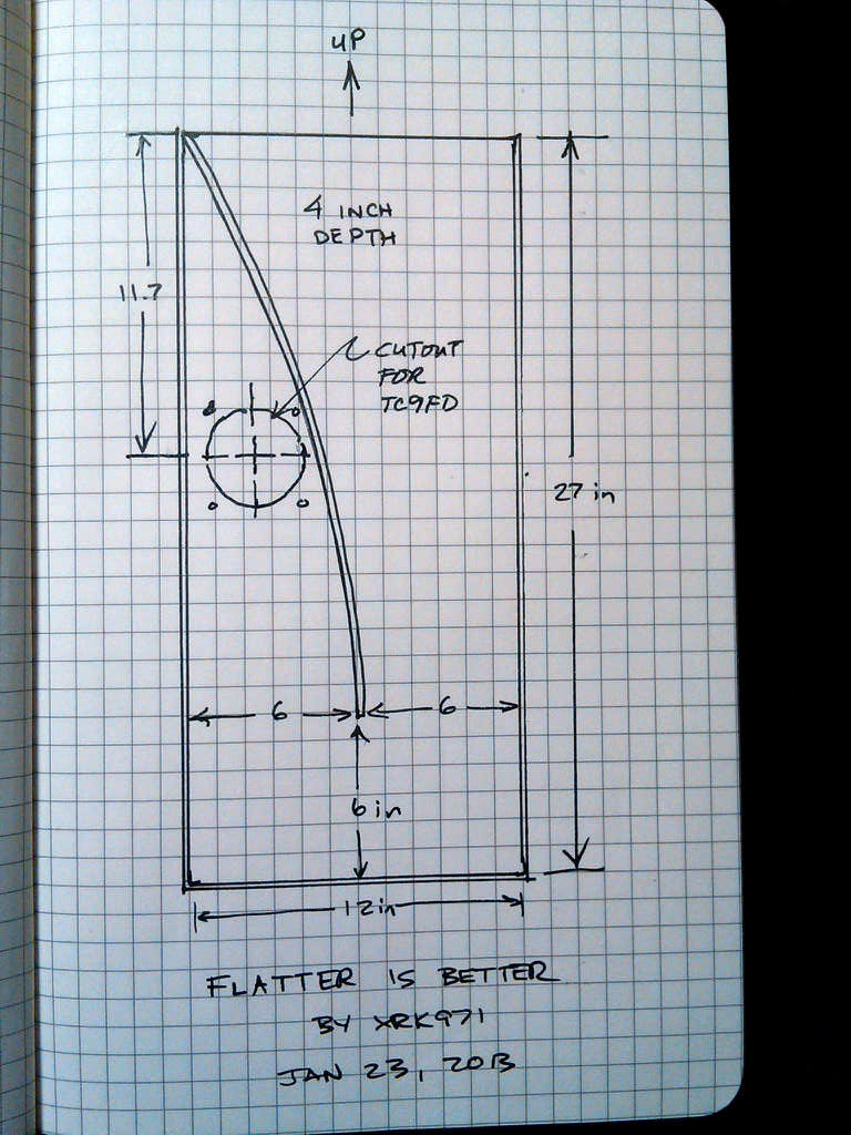
For those wishing to build this out of wood. You can still use plywood (I would use 1/4 in thick to keep it light so it can be hung on wall). Use the foam core just for the internal diagonal as it is easy to curve by scoring lines on the concave side.
Flatter is Better Plan for Vifa TC9FD driver. What is not shown are numerous vertical braces every 2 to 3 inches, braces would be aligned parallel to direction of flow (diagonal in the corners). Probably 25 to 30 2 in wide x 4 in tall pieces of 3/16 in thick foam core braces glued with hot melt to back panel and then with PVA to front baffle. Use 90 deg square guide to ensure braces are vertical and square when fastening to back panel with hot melt glue. I would put stuffing in closed end and loosely up the 180 deg turn. Adjust to taste. I think that there may be extensive bass with this design and it may require more stuffing than usual.
For those wishing to build this out of wood. You can still use plywood (I would use 1/4 in thick to keep it light so it can be hung on wall). Use the foam core just for the internal diagonal as it is easy to curve by scoring lines on the concave side.
Last edited:
Hi GM,
Thank you for getting back to me.
Haha, I see what I have done.
The excel Bib calculator that I downloaded had the specs for the old FE206e driver but not the new one.
Boy am I ever glad that I asked before I started cutting wood.
(Measure (check?) twice, cut once)
With one inch build material I now come up with the same ones.
External dimensions of 12*16*76.
At present I have an Cambridge integrated amp and a Sonic T-amp (that I plan to modify) but think that something along the lines of a bottlehead S.E.X. lamp is on the way. Basically, I'll build the speakers and then tailor the amp to them.
So if I interpret what you are saying correctly, the presswood or particleboard is a bad idea for the rear panel and should build it with 1 inch ply to increase the stiffness of the cabinet. If need be, I can adjust damping with felt or stuffing. What about the slant? Optimally, do I want particle board or plywood?
-andre-
Greets!
Hmm, the only specs I have are the published ones, which = 75.24” H, x 9.982” W x 14.117” D [inside].
45 Hz Fs
2.51 ft^3 Vas
0.1864 Qts
So, what specs are you using?
GM
xrk971, I know you love your curves, and with the high Qts of the Vifa driver it might work fine, but for drivers with lower values it might not.
You are after all starting with a clearly parabolic horn going into an exponential-ish, it's almost an MLTQWT with a horn on the mouth.
Why not just make a V shaped divider, that would also take care of a lot of the bracing?
You are after all starting with a clearly parabolic horn going into an exponential-ish, it's almost an MLTQWT with a horn on the mouth.
Why not just make a V shaped divider, that would also take care of a lot of the bracing?
Last edited:
I thought about the inverted V divider (if that is what you mean by a V shaped divider - good point about bracing), would that not split the mouth into two horns and thereby change the lowest freq the horn can reach due to reduction of the mouth circumference. The curved single divider wall is merely to provide additional clearance for the driver. One option is to make the V divider lower than the top of the box so that the two horns can merge back into one and maybe provide the larger horn mouth?
- Home
- Loudspeakers
- Full Range
- Terry Cain's BIB -why does it work and does anyone have those Fostex Craft Handbooks?