lol as far as the screws go... the theme was leftovers... i used scrap mdf, scrap veneer, and $3 dollars worth of speakers. i couldnt justify any money on screws so i just grabbed some i had layin around.
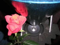
for nsb mods.. i coated them in elmers glue/water solition, and burned a small hole in the dust cap. i want to eventually put phase plugs in them. for $3 im very satisfied
for nsb mods.. i coated them in elmers glue/water solition, and burned a small hole in the dust cap. i want to eventually put phase plugs in them. for $3 im very satisfied
gpapag said:(continued)
It has ended up sounding balanced, no boxiness at all, bodied, non fatiquing and pleasantly heard from other rooms of the house (two floored). Family-wife and two daughters-fell in love with them (i.e. they tend to use them as well).
See next
George
Just curious, have you measured the response? I would expect slight drop in the higher frequencies even though the JX92 itself has a rise.
Hi all
I apologize to soonqsc and Rudolf for not responding so far. (I am in the process of recovering my home PC after a malicious infection. Three days ago i disabled the firewall for a minute and ...you can imagine. It seems that this year I am going to fight a lot with PC troubles. Four hours before the New Year's Eve my hard disk crashed. The next two days i was playing the fach-idiot!). I was watching the forum from my work PC though.
So, I have not measured the response yet. But you can safely bet that there is such a drop. This speaker placement can provide this benefit. I don't like listening to JX92S on axis.
Now as you know, the amount of dropping depends on some factors: reflecting/arbsorbing properties of reflector (form of reflector, geometric details of reflector, material of reflector, surface finish of reflector, placement of reflector relative to driver), reflecting/arbsorbing properties of surfaces close to reflector (upper surface of speaker box, walls).
Some of these factors work uniformly across a large part of the frequency spectrum, some are more selective.
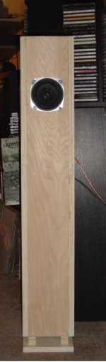
Up to now I have tried 4 reflector types and a few variations on each. The one that you saw on the picture is one variant of the cone type.
It has some good virtues (massive, easy to fabricate, looks good), but many things are under consideration and investigation.
For start, the angle that Rudolf questioned. It is 55 degrees. Cone's height is 290mm (910mm upper periphery) Not a gold angle or proportion, nor optimized. I made a rough choice based on the assumption that this cone will not act as an “abrupt” surface in front of the driver and that it will not reflect much of the sound back against the driver and the upper side of the box. Indeed, compared to another cone I tried (90 degrees, height 200mm) it sounds more “open”, but this is not conclusive due to differences in materials used. Later on, I will make a 90 d. with the same materials.
Other forms of reflectors are more focusing, thus more acoustically “efficient” but quite difficult to fabricate as rigid structures and aesthetically acceptable at the same time. Some are less diffraction prone. I will keep on working on this for a long time, I know.
Another open topic is the use of an electronic filter. I have not tried any yet. I will settle for a certain reflector first.
This was meant to be an entertaining as well as a multidiscipline educative project.
Regards
George
I apologize to soonqsc and Rudolf for not responding so far. (I am in the process of recovering my home PC after a malicious infection. Three days ago i disabled the firewall for a minute and ...you can imagine. It seems that this year I am going to fight a lot with PC troubles. Four hours before the New Year's Eve my hard disk crashed. The next two days i was playing the fach-idiot!). I was watching the forum from my work PC though.
So, I have not measured the response yet. But you can safely bet that there is such a drop. This speaker placement can provide this benefit. I don't like listening to JX92S on axis.
Now as you know, the amount of dropping depends on some factors: reflecting/arbsorbing properties of reflector (form of reflector, geometric details of reflector, material of reflector, surface finish of reflector, placement of reflector relative to driver), reflecting/arbsorbing properties of surfaces close to reflector (upper surface of speaker box, walls).
Some of these factors work uniformly across a large part of the frequency spectrum, some are more selective.
Up to now I have tried 4 reflector types and a few variations on each. The one that you saw on the picture is one variant of the cone type.
It has some good virtues (massive, easy to fabricate, looks good), but many things are under consideration and investigation.
For start, the angle that Rudolf questioned. It is 55 degrees. Cone's height is 290mm (910mm upper periphery) Not a gold angle or proportion, nor optimized. I made a rough choice based on the assumption that this cone will not act as an “abrupt” surface in front of the driver and that it will not reflect much of the sound back against the driver and the upper side of the box. Indeed, compared to another cone I tried (90 degrees, height 200mm) it sounds more “open”, but this is not conclusive due to differences in materials used. Later on, I will make a 90 d. with the same materials.
Other forms of reflectors are more focusing, thus more acoustically “efficient” but quite difficult to fabricate as rigid structures and aesthetically acceptable at the same time. Some are less diffraction prone. I will keep on working on this for a long time, I know.
Another open topic is the use of an electronic filter. I have not tried any yet. I will settle for a certain reflector first.
This was meant to be an entertaining as well as a multidiscipline educative project.
Regards
George
Attachments
gpapag said:Hi all
I apologize to soonqsc and Rudolf for not responding so far. (I am in the process of recovering my home PC after a malicious infection. Three days ago i disabled the firewall for a minute and ...you can imagine. It seems that this year I am going to fight a lot with PC troubles. Four hours before the New Year's Eve my hard disk crashed. The next two days i was playing the fach-idiot!). I was watching the forum from my work PC though.
So, I have not measured the response yet. But you can safely bet that there is such a drop. This speaker placement can provide this benefit. I don't like listening to JX92S on axis.
Now as you know, the amount of dropping depends on some factors: reflecting/arbsorbing properties of reflector (form of reflector, geometric details of reflector, material of reflector, surface finish of reflector, placement of reflector relative to driver), reflecting/arbsorbing properties of surfaces close to reflector (upper surface of speaker box, walls).
Some of these factors work uniformly across a large part of the frequency spectrum, some are more selective.
Up to now I have tried 4 reflector types and a few variations on each. The one that you saw on the picture is one variant of the cone type.
It has some good virtues (massive, easy to fabricate, looks good), but many things are under consideration and investigation.
For start, the angle that Rudolf questioned. It is 55 degrees. Cone's height is 290mm (910mm upper periphery) Not a gold angle or proportion, nor optimized. I made a rough choice based on the assumption that this cone will not act as an “abrupt? surface in front of the driver and that it will not reflect much of the sound back against the driver and the upper side of the box. Indeed, compared to another cone I tried (90 degrees, height 200mm) it sounds more “open? but this is not conclusive due to differences in materials used. Later on, I will make a 90 d. with the same materials.
Other forms of reflectors are more focusing, thus more acoustically “efficient?but quite difficult to fabricate as rigid structures and aesthetically acceptable at the same time. Some are less diffraction prone. I will keep on working on this for a long time, I know.
Another open topic is the use of an electronic filter. I have not tried any yet. I will settle for a certain reflector first.
This was meant to be an entertaining as well as a multidiscipline educative project.
Regards
George
The drop in high frequency would be due to different energy dispersion pattern from mostly 30 degrees within the speaker center to many more time the surface area.
You have the right concept on the angle, I don't think you will get better performance with the 90 degree configuration. I properly shaped parabolic curve might give slightly better performance, this is where it becomes a bit tricky.
No need to do so, Georg. I hope the worst of this year already lays behind.gpapag said:I apologize to soonqsc and Rudolf ...
")
And thanks for that in-depth explanation.
All arguments agreed uponNow as you know, the amount of dropping depends on some factors: reflecting/arbsorbing properties of reflector (form of reflector, geometric details of reflector, material of reflector, surface finish of reflector, placement of reflector relative to driver), ... Up to now I have tried 4 reflector types and a few variations on each.
People are rare that look deeply into cone design for omnidirectional dispersion. So I´m looking very much forward for the final results you may find. Hope you will publish them here.
Keep the project entertaining and educative for all of us.
Regards
Rudolf
Hi folks,
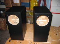
Here's my first DIY speaker project. FR125S in a pair of mass-loaded, tapered transmission line, bipoles. (Would that be CSSFR125SMLTTLBP?) I used one 5x5' sheet of Baltic birch with minimal leftovers.
I went for wide and shallow, to keep the drivers close to each other, thinking that might reduce bipole phase issues. Also, I like the wide look and it encroaches less into my living room.
I'm still playing around with stuffing the port with foam, though it doesn't seem to be making a huge difference. I have yet to get the drivers to show any signs of over-excursing from frequencies below the tuning frequency. I did tune them very low however, as I wanted a gentle roll off rather than flat-then-plummet response.
Many thanks to DIY Audio for ideas and to MJK for his worksheets.
Here's a photo from my apartment hallway. I'm afraid my living room is a candidate for the "how messy is your office" thread at the moment.
Max
Attachments
BD Pipes with Radio Shack 40-1197
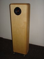
I have finally finished a speaker projet! The BD-Pipes is a bi-pole TQWP designed by Bert Doppenberg. It houses four Radio Shack 40-1197 (FE-103) 4" drivers and there are no filters or BSC.
The drivers are still breaking in, but thus far, I am very impressed with the sound. The sound is very detailed and the drivers are fast. The upper mid-range is a little bright, but I am hoping that this will change as the drivers break in. The imaging is excellent and the response is quite extended. I will eventually try some tweeters. I am a little surprised with the amount of bass these little 4" drivers produce. So far I am very pleased with the results. The speakers are very revealing and now I feel compelled to upgrade my preamp and CDP.
I have some pictures of the constuction posted in this thread:
http://www.diyaudio.com/forums/showthread.php?s=&threadid=70974
Overall, I am very pleased. Paint with come in the summer and I should get a webpage up in the next few weeks.
Attachments
"Now as you know, the amount of dropping depends on some factors: reflecting/arbsorbing properties of reflector (form of reflector, geometric details of reflector, material of reflector, surface finish of reflector, placement of reflector relative to driver), reflecting/arbsorbing properties of surfaces close to reflector (upper surface of speaker box, walls). "
You didn't mention perhaps the biggest reason - a driver with flat on-axis response has it only by virtue of the increasing directivity,
The power response (total output) decreases with increasing freq, so when you spread the treble all around, the high end will be rolled off.
You didn't mention perhaps the biggest reason - a driver with flat on-axis response has it only by virtue of the increasing directivity,
The power response (total output) decreases with increasing freq, so when you spread the treble all around, the high end will be rolled off.
Illusus said:maxro- 'monkey coffins'. I like them.
Thanks.
Maybe I should put a photo of a monkey face on the back of the rear driver. Then, if someone were to remove the front driver it would creep the hell out of them.
Maybe not.
I forgot to mention that the drivers are attached to each other by aluminum rods connecting the flange mounting bolts. The rods "float" in holes in the cabinets and the driver flanges are sealed with blutack.
Max
maxro said:Here's my first DIY speaker project. FR125S in a pair of mass-loaded, tapered transmission line, bipoles. (Would that be CSSFR125SMLTTLBP?) I used one 5x5' sheet of Baltic birch with minimal leftovers.
Very interesting implementation with the driver where the port would be & the port where the driver would be -- if you were doing an ML-Voigt.
dave
PS: can i post this project with drawings on my box-plan pages?
planet10 said:can i post this project with drawings on my box-plan pages?
Please do. If you need a better image, let me know. I created the drawing in Qcad and it is saved as a .dxf.
A few notes:
Material is one 5'x5' sheet of 15mm baltic birch.
The rods connecting the drivers are 1/4" aluminum solid rod, cut to 161mm (slightly longer than the recesses in the cabinets are apart) and end drilled and tapped for 5mm shallow head bolts. Make these after the cabinets are all glued up so that you can get the length just right. They are not attached to the cabinets, just slid through holes in them.
Drivers are sealed to the cabinets with Blutack.
The voids at the bottom corners and at the top end of the line are filled with fine sand.
The cabinets are stuffed with about 6oz of regular old polyester pillow stuffing each. The stuffing has to be put in before gluing the cabinets together as I don't think it would be possible to get the stuffing into that top corner. The area around the drivers has no stuffing, but I glued some 1/2" thick "unknown fibre" (mostly cotton) felt across the top and about 8" down the side walls
The ports are 2" black plastic ABS pipe.
Internal wiring is a single run of CAT 5. Drivers are wired Parallel.
The feet are made of 3/4" square aluminum stock. I got lazy and did not end up notching them to cup the cabinets' bases as shown in the drawing.
All cabinet edges are 45 degree chamfered the full thickness of the plywood.
Any ideas for albums which might make my drivers overexcurse from frequencies too low for the port? I've been trying all sorts of stuff, and have yet to see the drivers 'pumping'. Not that I want to ruin my drivers, I just want to know their limitations.
Here's the MJK Mathcad simulated response:
http://www.diyaudio.com/forums/showthread.php?postid=809967#post809967
Max
maxro said:about the single driver matching service I read about somewhere, did that ever happen?
I have a single Wharfedale Super 12/CS/AL that needs a mate. Got any? Want one?
I have a working database, and at least a 100 single drivers, but the "Single Driver Mating Service" hasn't hit the top of the lengthy queue of unfinished projects yet.
An single alnico Super 12 fetches reasonable money on eBay, a ceramic one not so much.
dave
Re: Fostex BK10 kit
Got a url to the web page? ... AC is delivering an unhappy face to anyone accessing the pic from outside their domain.
dave
(Note: if you already have the pic in your browser cache, it may show the right image)
FattyFatty2x4 said:
Got a url to the web page? ... AC is delivering an unhappy face to anyone accessing the pic from outside their domain.
An externally hosted image should be here but it was not working when we last tested it.
dave
(Note: if you already have the pic in your browser cache, it may show the right image)
- Home
- Loudspeakers
- Full Range
- Full Range Speaker Photo Gallery