I'm doing the plans right now and I wondering where the port should be located, and if I can replace the circular port by a linear port, keeping the same surface and volume, because linear ports, which can be seen on most TQWTs are less likely to produce air flow noises than circular ports like BR.
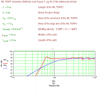
You also told me the formula for length was not correct, then, I don't know if the length given in the geometry page of the ML-TQWT sheet (picture) can be applied to the straight face length, the tapered face or if this value is raw and must be corrected.
Maybe my questions are a little boring, but I'm a beginner") and of course if my design works I will put it on my website so everybody can reproduce it
and of course if my design works I will put it on my website so everybody can reproduce it 
PS : I don't know why but I cannot joint a picture, though it's smaller than 100KB. It's visible here http://youyoung21147.site.voila.fr/dataMLTQWT2.PNG
You also told me the formula for length was not correct, then, I don't know if the length given in the geometry page of the ML-TQWT sheet (picture) can be applied to the straight face length, the tapered face or if this value is raw and must be corrected.
Maybe my questions are a little boring, but I'm a beginner
and of course if my design works I will put it on my website so everybody can reproduce it PS : I don't know why but I cannot joint a picture, though it's smaller than 100KB. It's visible here http://youyoung21147.site.voila.fr/dataMLTQWT2.PNG
Re the port, technically you should be able to replace the tubular port with a linear / slot port, but I doubt you'd find much advantage, and quite possibly the reverse -Bob Brines in particular has found that these increase ripple in the mid-range over the tubular type, and has abandoned them in favour of the latter. Note also that Martin King doesn't use them either. Having built and modelled a few pipes - ML-TL, TQWT, ML-TQWT etc., I wholeheartedly concur. Airflow noise in a port tends to be less of a problem with TLs than BR designs; you'd have to ask Martin or Bob exactly why, (I suspect that it's down to the nature of the internal resonance and pressure). So long as it's of reasonable proportions (and they tend to be large for TLs, it shouldn't be an issue.
Hi,
have you had a look at Bob´s speaker stuff?
Go through the "tutorials". Quite helpful indeed for the mathcad sheets.
The design you posted shows quite big ripple still.
(set densitiy to 0.0 and you know what I mean)
Generally when you need to overstuff an enclosure to keep the ripple down the design is basically "flawed".
IMO the line lenght for such a driver is much too long.
From what I´ve read I try not to go below 0.7*fs.
Try line lenght 33.5, position 0.34, port 0.8*2in.
Mind you the tuning is still slighty too deep and you have to keep in mind that SPL will be very limited.
greets
Basic rule of thumb that Bob created as a starting point for TQWT, and it's a useful generic guide for starting with MathCad simulations, which can then help refine things:
So = (or is greater than) Sd
Sm = 4Sd
Ap (port area) = 1/2 Sd
D (height of the driver) = 1/2 L (pipe length)
I usually find that the driver height works best between 1/2 and 1/3 the pipe length. Remember that stuffing should only be used to damp out the higher harmonics -that's what it's there for. As suggested above, and by Bob, if you have to go over about 0.3lbs per cubic foot, there's something awry with the basic design. My view is the least you can get away with the better.
After many trials, and following joensd rules, I obtain something much better with no stuffing.
Although the results are correct, I wonder if placing the driver at 2/3 of the pipe will create an acoustic short circuit between the port and the driver, and therefore makes the simulation incorrect.
As anyone ever tried to put the driver at more than 1/2 pipe ?
Although the results are correct, I wonder if placing the driver at 2/3 of the pipe will create an acoustic short circuit between the port and the driver, and therefore makes the simulation incorrect.
As anyone ever tried to put the driver at more than 1/2 pipe ?
Attachments
MJK said:
Yes, but it is a little more complicated then just entering a value on the first page. To model variable stuffing densities you need to edit the column of densities on the second page, the last column on the right. You can enter new values of just add a mulitiplier to the rigth of the ":=" signs. If you enter a new value remember to use the appropriate units (kg/m^3 or lb/ft^3).
Martin,
I noticed some Theil speakers have long and narrow port along the front. Is it possible to model something like that?
youyoung21147 said:After many trials, and following joensd rules, I obtain something much better with no stuffing.
Although the results are correct, I wonder if placing the driver at 2/3 of the pipe will create an acoustic short circuit between the port and the driver, and therefore makes the simulation incorrect.
As anyone ever tried to put the driver at more than 1/2 pipe ?
Are we talking about height from the base, or from the closed end? If it's the former, setting the driver at 1/3 pipe length will cancel the null at F3, but the geometry has an effect as well, as I'm sure you'll have discovered by now.
If it's the latter -well, none of the pipes I've built so far have needed the driver mounting lower than 1/2 length, though if required they can be mounted lower. I seem to recall Bob suggested such a layout for one of the larger Fostex drivers in a TQWT -FE206 or 207, I forget which, and that, with a line length of 60 inches, needed the driver mounting at around 26 or 27 inches above the base I believe (though I don't think he was overly enarmoured by the idea, frankly).
May I suggest that you are trying to force a driver into a cabinet that is not optimum? With the high Qts of the 871, you would be much better served by trying a negative taper pipe -- a more or less conventional TL. You have managed to smooth out the FR curve, but you have a huge peak at cut-off with a precipitous drop, and at a very unfortunate frequency. You are gong to have one-note bass that won't quit. Basically, the pipe is too efficient with too narrow a band width.
A technical note or two: It is correct to place the driver at 1/3 the ACOUSTIC length of a TQWT in order to suppress the third harmonic (first overtone). However, with a zero So pipe, this is 1/2 the PHYSICAL length of the pipe. Reducing the port area causes further movement of the PHYSICAL position of the 1/3 wave length.
Placing the port, circular or slot, up from the bottom of the pipe smooths out the FR curve. Particularly with a straight pipe, there are very strong 9-13 harmonics. moving the port so as to suppress the 11 harmonic, along with slight movements of the driver position smooths the the entire FR curve.
Bob
You are right Bob ! I were trying to force it because I didn't notice the length was so important, as I have the metric system in my contry. I know it has a high Qts not very suitable for a QWT but I'll manage with it. Anyway, the Fostex are worse on this point.
These speakers are intended for Home theater applications, so I have a subwoofer which I would like not to use above 100Hz because it's a **** from a cheap JBL kit, so I don't mind if the FR draws a cliff after the F3 point. But I know loading a speaker too much makes it "slow" and "soft'
I have made new trials and the curve I obtain is better, and still goes under 100Hz.
I also tried inverted taper but it doesn't give good results.
You tell that the height of the port has an importance to cancel undesired resonnances, so is there a formula or something else to calculate this height ?
Attachments
Ok. Use metric units in you simulation. Mathcad actually works in metric anyway. Then you won't have problems trying to visualize English lengths.
To see what is happening in the harmonic structure of the pipe, you need to look at the port/driver response, which is two graphs farther down the page. You will see that you don't have the 3rd harmonic completely suppressed. As to the higher harmonics, I'm afraid that the 9-13 harmonics may be off of the graph to the right because of the high Fp of this pipe. It is no big deal, though, since frequencies this high are easily suppressed by the stuffing. Just center the port 5-6cm up from the bottom. (You will need to use the "ported" worksheet to adjust the port position. You can do it with the "sections" worksheet, but that is a pain.)
Bob
I think I've got it now !
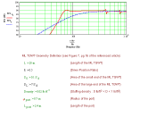
Moving the port 3' above the bottom linearizes both the far field FR and the port output.
I'm ready to do the plan but I still have, I hope the last, question : when you give Mathcad the length of the TQWT, what is it based on ? Is it the total length of the line following the internal face that holds the speaker, or the tapered face, or an average of both ?
http://youyoung21147.site.voila.fr/dataMLTQWT20port.PNG
I usually set the length equal to the average, the line down the middle of the TQWT areas.
How do these graphs compare to the MathCad model of your first speaker. the one that you built?
Also, remember that these calculations do not account for the baffle step loss at low frequencies so you may still need some form of corrections filter.
How do these graphs compare to the MathCad model of your first speaker. the one that you built?
Also, remember that these calculations do not account for the baffle step loss at low frequencies so you may still need some form of corrections filter.
I noticed some Theil speakers have long and narrow port along the front. Is it possible to model something like that?
With the versions of the worksheets on my site right now, the assumption is that the cross-sectional areas are round (or square). To model a slotted port, that has one dimension much greater then the other, requires some different equations starting with the acoustic impedance of the open end of the slot. The floor boundary condition also becomes very important if the slot is right at the bottom of the enclosure. My newer back loaded horn worksheets that I am currently working on have some of this math already worked out, but probably not all of it yet.
There is no comparison with the speaker I built, but between different simulations I did with your worksheets. The speaker I built has just been measured with a microphone but it's not good at all anyway.
I have made the plans following your rules and hope it'll work fine.
I know about baffle step problems, but the speakers will be placed near corners and moreover, I have a tonality adjuster on my amplifier (bass pot.).
Here is the plan, made for 10mm MDF. You can see that the triangle formed can't be senn on the face but on the side, contrary to your Fe164 ML-TQWT. I suppose it has no influence on the sound
http://youyoung21147.site.voila.fr/DSCF1724.JPG
I've just cut the wood for the second prototype, and begun to assemble it.
Unfortunately, it is late and my parents were angry to hear the drill in the garage and imaginating all the mess I made though I had only 6 holes left to do
I will continue and end the assembly tomorrow, and make the first measurements.
You can't imagine how impatient I am !
So good night everybody, and come there to have news tomorrow !
http://youyoung21147.site.voila.fr/DSCF1726.JPG
Unfortunately, it is late and my parents were angry to hear the drill in the garage and imaginating all the mess I made
though I had only 6 holes left to do I will continue and end the assembly tomorrow, and make the first measurements.
You can't imagine how impatient I am !
So good night everybody, and come there to have news tomorrow !
http://youyoung21147.site.voila.fr/DSCF1726.JPG
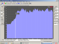
I've just built the enclosure this afternoon and made measurements
As you can see on the FR graph, linearity is excellent but the bass response is quite far from the simulation, although my cabinet is not well sealed and the port made with a thick Bristol sheet at this time but I know I won't be able to get the expected response anyway.
I think this enclosure will be perfect as a center speaker, designed to reproduce voices and not bass
Attachments
I've sealed the enclosure correctly but I just get 2Hz more on the response.
I didn't measure the T/S parameters myself, but used the manufacturer's one.
I know it's not the best choice but I doubt I'd obtain tighter results myself,as I don't have a special room for that and a well-sealed box either.
I didn't measure the T/S parameters myself, but used the manufacturer's one.
I know it's not the best choice but I doubt I'd obtain tighter results myself,as I don't have a special room for that and a well-sealed box either.
- Status
- This old topic is closed. If you want to reopen this topic, contact a moderator using the "Report Post" button.
- Home
- Loudspeakers
- Full Range
- Strange TQWT behavior with the small TangBand W3-871S