Hello everybody !
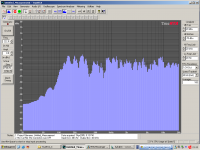
Very impressed by a french TQWT kit seen in a loudspeakers shop, based on Fostex FX-120, I decided to study and build my own TQWT enclosure for home-cinema speakers. I choosed the TangBand W3-871S for its perfectly flat frequency response and its good 0,6 qts regarding to its small size. I spent very much time on the Internet, studying the behavior of quarter wavelengthes, and looking for well-working plans, to have an overview and extrapolate a "building theory". I knew it would be a harsh job, but I have been quite disapointed by the result, almost the same as in a sealed enclosure. . (look at the picture, taken with a calibration mic and True RTA 3)
The box has been built with the driver placed at 1/3 of the length, the length is 1/4 of the Fr (110Hz) and the port has the same surface as the driver Sd. The box is two times deeper than the loudspeakers diameter, as I can see it on every TQWT enclosures I saw.
I then saw the "needles" enclosure for VISATON FRS8 and was surprised to see it was tuned at 50Hz, which goes completely against the tehory !
So, if anyone could explain me this, I'd be glad because I don't understand why would'nt it work with me, and why an ultra-low-tuned enclosure works
")
Very impressed by a french TQWT kit seen in a loudspeakers shop, based on Fostex FX-120, I decided to study and build my own TQWT enclosure for home-cinema speakers. I choosed the TangBand W3-871S for its perfectly flat frequency response and its good 0,6 qts regarding to its small size. I spent very much time on the Internet, studying the behavior of quarter wavelengthes, and looking for well-working plans, to have an overview and extrapolate a "building theory". I knew it would be a harsh job, but I have been quite disapointed by the result, almost the same as in a sealed enclosure.
. (look at the picture, taken with a calibration mic and True RTA 3)The box has been built with the driver placed at 1/3 of the length, the length is 1/4 of the Fr (110Hz) and the port has the same surface as the driver Sd. The box is two times deeper than the loudspeakers diameter, as I can see it on every TQWT enclosures I saw.
I then saw the "needles" enclosure for VISATON FRS8 and was surprised to see it was tuned at 50Hz, which goes completely against the tehory !
So, if anyone could explain me this, I'd be glad because I don't understand why would'nt it work with me, and why an ultra-low-tuned enclosure works
Attachments
Talking about "against the theory": have a look here:which goes completely against the tehory !
http://www.visaton-bausaetze.de/hifi/index.htm?/hifi/lancetta.htm
Also have a look here :
http://www.diyaudio.com/forums/showthread.php?threadid=33101&perpage=10&highlight=&pagenumber=5
I built the QWT posted in post4. A picture and measurements can be found in post44.
Looks similar to your graph. I also expected a little bit more below 100Hz but I can tell you the difference between the QWT and a BR I tried is not small. Although the QWT doesn´t go much deeper it does so with more "clarity" in the bass.
Any hints to what enclosure you used?
greets
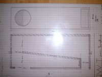
Here is the picture of the plan. The quality is bad due to the obligation of small size. As I don't reinstalled Photoshop, I couldn't compress it more.
It's a classical folded TQWT with frontal port. Notice the ratio of the dimensions of this port are the ones of the gold number
I saw your speaker, but you seem to have put a much smaller port that looks like a bass reflex The frequency response is like mine, and I tried to put a reflex port, because using CAAD4.1, I could expect a 65Hz f3 but that's totally wrong ! The reflex port just "kills" the subtles details of the sound. I hate reflex loading anyway for hifi purposes.
It's a classical folded TQWT with frontal port. Notice the ratio of the dimensions of this port are the ones of the gold number
I saw your speaker, but you seem to have put a much smaller port that looks like a bass reflex
The frequency response is like mine, and I tried to put a reflex port, because using CAAD4.1, I could expect a 65Hz f3 but that's totally wrong ! The reflex port just "kills" the subtles details of the sound. I hate reflex loading anyway for hifi purposes.Attachments
i think there is another plan "cyburgs needle" (http://www.diyaudio.com/forums/showthread.php?s=&threadid=47403&highlight=) which deals with a lower tuned enclosure for the 871 . please post your opinions if you build it.
regards
regards

The box has been built with the driver placed at 1/3 of the length, the length is 1/4 of the Fr (110Hz) and the port has the same surface as the driver Sd. The box is two times deeper than the loudspeakers diameter, as I can see it on every TQWT enclosures I saw.
It's a classical folded TQWT with frontal port. Notice the ratio of the dimensions of this port are the ones of the gold number
Unfortunately, it would appear that you used the classic rules of thumb and probably got the classic results. The classic TQWT does not perform very well. If you want better performance, you should try some of the newer methods for designing this type of enclosure.
Also, if you use a cheap driver then right from the start you are probably limiting the potential of the final results. You get what you pay for in life. Try one of the Fostex drivers as a minimum.
RatherSorry to be so brutal...
Maybe something special or whatever (great imaging, almost perfect treble response without being harsh........)?But the real question is what the **** are you waiting from a small cheap speaker ?
I personally was surprised and IMO I got plenty of Hifi.If you are waiting surprise perhaps it could be ok, but if you are waiting HiFiifi...
If you´re talking about bass..., no you can´t expect wonders.
Unfortunately you (almost always) get what you pay for but for a 3" you get quite a bit with the Tangband.Also, if you use a cheap driver then right from the start you are probably limiting the potential of the final results. You get what you pay for in life. Try one of the Fostex drivers as a minimum.
I´ve only the Fostex FE-167E to compare with and I can tell you that it has weaknesses the Tangband hasn´t and is just as well a compromise. And to not sound negative in any way both are great speakers for the money.
Then what do you call "new methods" ?
The TQWT with the FX-120 (that I'm also building from a plan) uses exactly the same techniques but goes down to 40Hz, which is pretty low for a 70cm high speaker !
I thought of tuning it down to half the Fr (55hz) but then there may be a dip between 150 and 50 Hz !
I also thought associating a transmission line on a bass reflex port, or putting a TL at the end of the existing TQWT.
What do yout hink about it ?
Then what do you call "new methods" ?
Accurate computer modeling and measuring of the raw drivers and the completed system. Analytical predictions before you build so that good design trade-offs can be made.
One question, how did you determine the length of your TQWT so that the quarter wave tuning was at 110 Hz? If you used the classic equation
L = 1/4 x (c / f)
then your initial length was wrong, your line is way too short. This equation only works for straight TL's. Also, by adding a restriction at the open end you have mass loaded the TQWT and lowered the quarter wave frequency. Did you account for this in your design?
I thought of tuning it down to half the Fr (55hz) but then there may be a dip between 150 and 50 Hz !
I also thought associating a transmission line on a bass reflex port, or putting a TL at the end of the existing TQWT.
You have "thought" about several ideas, now you need to engineer the idea so it becomes a design concept. Reading the web and scaling other unheard designs is not the approach I would take. Looking at other designs for ideas to explore is fine.
I didn't take into consideration the fact that there was a restriction at the port but when drawing the plans, I took into consideration it was a folded tqwt, and calculated the length from the middle of each part, in the middle, which makes an average length so I suppose it is almost the same (I hope)
I tried yesterday evening to increase the length by putting thick paper sheets to form a tunnel after the port, but the result was acoustically worse, not for the bass response but for the sound quality.
I just realize that I didn't even post a photo of the prototype. It is made of 10mm MDF, I suppose it rigid enough
Here it is : http://youyoung21147.site.voila.fr/DSCF1719.JPG
I'm still searching the net to find exotic or well-working enclosures, and I'll also try your MathCad worksheets, but then I need MathCad . I hope I won't have to spend too much timme cutting wood, because I don't have much time as a student
I tried yesterday evening to increase the length by putting thick paper sheets to form a tunnel after the port, but the result was acoustically worse, not for the bass response but for the sound quality.
I just realize that I didn't even post a photo of the prototype. It is made of 10mm MDF, I suppose it rigid enough
Here it is : http://youyoung21147.site.voila.fr/DSCF1719.JPG
I'm still searching the net to find exotic or well-working enclosures, and I'll also try your MathCad worksheets, but then I need MathCad
. I hope I won't have to spend too much timme cutting wood, because I don't have much time as a student I took into consideration it was a folded tqwt, and calculated the length from the middle of each part, in the middle, which makes an average length so I suppose it is almost the same (I hope)
That sounds like the correct way to calculate the length. The point I was trying to make is that calculating a tuning frequency based on only the length does not work for a TQWT. You need to account for the expansion which raises the tuning frequency. Using the equations
f = 1/4 x (c / L)
or
L = 1/4 x (c / f)
is probably the biggest and most common mistake made by TL or TQWT builders. These equations are only valid for a straight constant cross-section TL and not for any enclosure design that is tapered, expanding, or restricted at the open end.
I need MathCad
There is a free version that can be downloaded from my models page. Most people use this to run the worksheets. The only restrictions are that you must use the version 8 worksheets and you cannot save your work beyond doing a screen capture and pasting the results into another document. Please read the notes on this page if you are using a PC that has a comma notation for a decimal point as a default.
Yes there is a free version of mathcad on your website I had never noticed before, although I know your (excellent by the way)website for quite long.
I tried the calculation sheets but only the one for DBR works. In the others, there is a bug concerning the calculation of the Qts : as the Qes is <1, Mathcad says "you may be dividing by zero" which is wrong, but it blocks the rest of the program
I changed my regional settings to set the . as decimal separation.
there is a bug concerning the calculation of the Qts
That is caused by the comma being used as a decimal point. This is a common problem. Since I have never had to make this change, I don't really know all of the steps involved to make the change. You need to make your computer recognize the period as a decimal point and this problem will go away.
No sorry I said nothing. I restarted my computer and now it works like the other sheets.
I'm just learning how to use the ML-TQWT sheet, and you did a wonderful work, as I can see it on your website !
I guess you have to enter the dimensions of your enclosure yourself, and then the sheet gives a simulation of the frequency response.
I'm just learning how to use the ML-TQWT sheet, and you did a wonderful work, as I can see it on your website !
I guess you have to enter the dimensions of your enclosure yourself, and then the sheet gives a simulation of the frequency response.
I guess you have to enter the dimensions of your enclosure yourself, and then the sheet gives a simulation of the frequency response.
Enter the driver T/S parameters and then the enclosure geometry. Remember the enclosure geometry is the air volume inside and not the outside dimensions. The model is of the air only. The first page is all that you need to edit, then scroll down to see the calculated SPL response.
That's so wonderful...
I suppose I have to define all the parameters on the first page, and even the length of the line. I'm starting to "play" with the different parameters and it's very pleasant. I hope I'll have an idea of the enclosure I will build befor the night, unless I won't be able to sleep
Just one question : is it possible to apply the parameters to a folded enclosure, respecting the taper and everything ?
Are you able to put different stuffing density at different locations to see how varying density throughout the line effects the results?
Yes, but it is a little more complicated then just entering a value on the first page. To model variable stuffing densities you need to edit the column of densities on the second page, the last column on the right. You can enter new values of just add a mulitiplier to the rigth of the ":=" signs. If you enter a new value remember to use the appropriate units (kg/m^3 or lb/ft^3).
Just one question : is it possible to apply the parameters to a folded enclosure, respecting the taper and everything ?
Yes, typically the wavelength of sound at these low frequencies is so long that the fold will not be "seen". When you get up above say 500 Hz, the geometry of the fold might become important. Just model the folded pipe as a straight pipe and try and design what you end up building with a smooth path around the fold.
I have jungled with all the parameters for 3 hours now and I obtain what seems to be the best compromise between linearity and bass extension. I kept a quite large port to prevent flow noises, because I don't want my speakers to sound like bass reflex enclosures
These parameters really let me think my TQWT was too short, but now, I will have some big enclosures
Tomorrow I'll do the plans because I'm too tired now, even if I'm impatient to build a second prototype !
These parameters really let me think my TQWT was too short, but now, I will have some big enclosures
Tomorrow I'll do the plans because I'm too tired now,
even if I'm impatient to build a second prototype !- Status
- This old topic is closed. If you want to reopen this topic, contact a moderator using the "Report Post" button.
- Home
- Loudspeakers
- Full Range
- Strange TQWT behavior with the small TangBand W3-871S