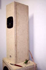
I've made another tower (ML TL) using the Fostex FE107E. This one sounds even better than the other one.
The first version ("Locust 0.5") had an ID height of 15 1/4". Playing around with Martin's MathCad worksheet, I determined that I could get the F6 down to 60 Hz by stretching it to 19 1/2". The mid bass was just a tad lower (1 or 2 decibels), but I reckoned that the BSC circuit could pull that up a little. For the intended purpose, I do not need much efficiency.
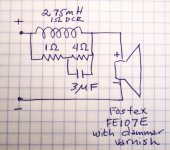
Your mileage may vary, because I had already varnished the speaker cones. That pulled the treble down. I was able to correct that by putting a 4.7 uF cap across the 4 ohm resistor in the BSC circuit. (See attached picture.) SpeakerWorkshop now shows that I've got pretty darned flat response all the way up, but with a wrinkle in the 10K-20K range. I've got the sub crossed over at about 63 Hz. On many recordings, it is not missed at all when I mute it.
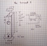
The whole thing is made from 3/4" MDF. The port is simply a 1" hole in the front panel, about an inch from the bottom (ID). Because of that, the front panel has to be 3/4" stock to make the port the right length. Construction could hardly be any simpler. All the side pieces are identical except for the holes. Six pieces are required per speaker:
4 pieces 5 1/2" X 21"
2 pieces 5 1/2" X 4"
The top 2/3 or so is stuffed very lightly with poly fiber. I used a Madisound input cup on the back, GB-CUP ($2.05 each). The inductor is Shoe-Gooed to the bottom. I glued the resistors and the cap to the input cup, to make it easy to change them if I decide to. The top half of the box is lined on three sides and top with 1/4" felt.
Total cost is about $50 US per speaker.
The first version ("Locust 0.5") had an ID height of 15 1/4". Playing around with Martin's MathCad worksheet, I determined that I could get the F6 down to 60 Hz by stretching it to 19 1/2". The mid bass was just a tad lower (1 or 2 decibels), but I reckoned that the BSC circuit could pull that up a little. For the intended purpose, I do not need much efficiency.
Your mileage may vary, because I had already varnished the speaker cones. That pulled the treble down. I was able to correct that by putting a 4.7 uF cap across the 4 ohm resistor in the BSC circuit. (See attached picture.) SpeakerWorkshop now shows that I've got pretty darned flat response all the way up, but with a wrinkle in the 10K-20K range. I've got the sub crossed over at about 63 Hz. On many recordings, it is not missed at all when I mute it.
The whole thing is made from 3/4" MDF. The port is simply a 1" hole in the front panel, about an inch from the bottom (ID). Because of that, the front panel has to be 3/4" stock to make the port the right length. Construction could hardly be any simpler. All the side pieces are identical except for the holes. Six pieces are required per speaker:
4 pieces 5 1/2" X 21"
2 pieces 5 1/2" X 4"
The top 2/3 or so is stuffed very lightly with poly fiber. I used a Madisound input cup on the back, GB-CUP ($2.05 each). The inductor is Shoe-Gooed to the bottom. I glued the resistors and the cap to the input cup, to make it easy to change them if I decide to. The top half of the box is lined on three sides and top with 1/4" felt.
Total cost is about $50 US per speaker.
Attachments
planet10 said:black varnish?
And that is MDF? Here we'd call that particle board... you should try a set in 1/2" ply.
Dammar varnish, with a final coat of ivory black artists' paint and dammar varnish. Seemed like a good idea at the time. MDF stands for medium density fiber board, which is particle board. Half inch ply wood? Why? I will seal and paint these when I get a round tuit. The port is supposed to be 3/4" long, and in this design it's just a hole in the front panel.
I'll be interested on your take on what the phase plugs do...
dave
I'll be interested to see if they ever get here.
")
Dave Jones said:MDF stands for medium density fiber board, which is particle board
Doesn't look like any MDF i've seen, LDF maybe.
Half inch ply wood? Why?
I'm pretty sure they will sound better
I'll be interested to see if they ever get here.
The post hasn't lost anything on me in the last 2 years (sample size >5000)
dave
The cabinets are made from chipboard which is not MDF.
Its made from wood chips, not wood pulp fibre like MDF.
Chipboard comes in various densities, and has variable density
itself, the surface layer being finer chips than the larger core.
Flooring grade chipboard is heavy, dense and strong, its also
pretty hard on tool edges that cut or shape it, due to the
random alignment of some very hard wood chips, whats
left from the knots in the chipped wood I presume.
sreten.
Its made from wood chips, not wood pulp fibre like MDF.
Chipboard comes in various densities, and has variable density
itself, the surface layer being finer chips than the larger core.
Flooring grade chipboard is heavy, dense and strong, its also
pretty hard on tool edges that cut or shape it, due to the
random alignment of some very hard wood chips, whats
left from the knots in the chipped wood I presume.
sreten.Paradise_Ice said:Most of the speakers boxes in the 70 and 80s were made from chip board right? very few ply and MDF whats that?LOL
Its still true for nearly every folded vinyl wrap speaker.
sreten.Dave Jones said:Well, I'm not going to throw them away.
We don't expect you to do that... we expect you to enjoy them. But with Locust 0.5 & 1.0, how far away can Locust 2.0 be?
dave
planet10 said:
We don't expect you to do that... we expect you to enjoy them. But with Locust 0.5 & 1.0, how far away can Locust 2.0 be?
dave
That is in the hands of United Parsel Service.
Dave Jones said:Well, I'm not going to throw them away.
I would never throw anything away am a horder!planet10 said:
We don't expect you to do that... we expect you to enjoy them. But with Locust 0.5 & 1.0, how far away can Locust 2.0 be?
dave
Chip board is a good material but when i lived in Ghana i notice that Chip board boxes can sound different in humid climates?
I hear people say they paint the inside of there plywood or varnish it, i think that is a better idea for chip board, i have never pressure tested a box, only intercoolers, I know David likes his Ply boxes, ask him for a treatment if you want to do something to make them last forever.
But i like the design it looks solid.

Paradise_Ice said:Chip board is a good material
I never did mention that there are some claiming chipboard is actually better sounding than MDF... the big advantages of MDF are that it is relatively cheap (in my case it is usually free) and holds a machined corner.
dave
planet10 said:
I never did mention that there are some claiming chipboard is actually better sounding than MDF... the big advantages of MDF are that it is relatively cheap (in my case it is usually free) and holds a machined corner.
dave
Yes your right, but you want to talk edges?
look at this
http://www.hiddenspeakers.com/product/149
This is just amazing, i have not heard this design but its so dame clever, i wish i had though of it

I know Steve Margolis would be interested in this design.
Has anybody in this forum used Glass for an enclosure?
Update: Just when I think it can't get any better, it gets better.
For a while I thought I had damaged the drivers by applying dammar varnish and paint. I A/B'd them vs. an original set. Although the varnished ones sounded very smooth, they were noticeably less bright than the pristine drivers. (It may be significant that the new drivers had not been broken in.) I decided to add a cap to the BSC circuit, turning it into a baffle-step and treble correction circuit (BSATC?). I tried a 2.2 uF. There was a dip in the upper midrange. I could see it plainly in the output of SpeakerWorkshop. I changed the cap to 4.7 uF. I thought that did the trick. But last night, I got a case of listener fatigue. There was now a narrow peak in lower treble.
So today I tried 3 uF caps. WOOHOO! The "air" is still there, but the nasty edge is 100% gone. Now I've really got the bug. I'm dreaming of Lowthers. I mean, how good can it get?
So the recipe is, 3 very light coats of of artists' dammar varnish, followed by one light coat of artists' ivory black paint with dammar varnish. Actually, if I did it again, I think I would mix up some banana-paper color paint. The response correction circuit is below.
Attachments
GM said:Ok, since efficiency isn't an issue, here's my suggestion for Locust 2.0.
Using 1/2" no-void plywood:
L = 34.3125"
SO/SL = 32.752 in^2
vent = 1.625" dia. = ~45Hz F6
driver down 12.125"
~5 ohms series R
GM
Thanks again GM. (GM essentially designed Locust 0.5.) How long is the port?
You're welcome!
1/2", hence the 1/2" material thickness requirement. I normally spec 3/4" min., but between the vent getting so big and this driver's modest output I figured if it wasn't stiff enough you could glue in a dowel or two.
Like Dave p10 though, I believe once you use a good grade of plywood such as Baltic Birch, you won't go back to the various flavors of chip/particle board, at least for wide BW drivers, pipes, horns, etc..
BTW, why didn't you parallel the bypass cap around all the resistance?
You've got a nice little system, but it gets soooo much better......
GM
1/2", hence the 1/2" material thickness requirement.
I normally spec 3/4" min., but between the vent getting so big and this driver's modest output I figured if it wasn't stiff enough you could glue in a dowel or two. Like Dave p10 though, I believe once you use a good grade of plywood such as Baltic Birch, you won't go back to the various flavors of chip/particle board, at least for wide BW drivers, pipes, horns, etc..
BTW, why didn't you parallel the bypass cap around all the resistance?
You've got a nice little system, but it gets soooo much better......
GM
Dave Jones said:
Thanks again GM. (GM essentially designed Locust 0.5.) How long is the port?
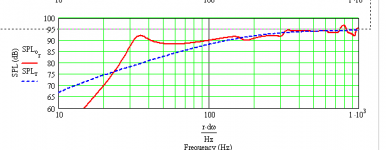
Of course, I could not wait for the answer to start fooling around with it. I put the numbers into Martin's software, and messed with the port length until I had a tuning around 40-45 Hz. (Does 1.75" sound about right.)
While the F6 is technically around where you said, the response starts falling off at about 400 Hz, which is roughly where the BSC kicks in. I think if I upped the resistance in that circuit, I could get the response danged near flat all the way down to 30Hz. Wouldn't that be impressive to get that kind of bass out of 4" drivers? And with all that added resistance, I could probably turn the amp (Rotel RA-02) up to about half way. That would make it easier to adjust the volume. Here's a picture of the frequency response. What do you think? Would the poor little drivers hop out of their moorings?
Attachments
I always calc the 'new' Qes and input it and the increased Re to see the theoretical half space FR, so assuming published specs, change Re/Qes to 12.6 ohms/0.746, rp = 0.812", Lp = 0.5" to see what I simmed.
If using measured specs, then calc your own Qes' and adjust Re, vent as required:
Qes' = Qes*(1+Rs/Rvc), where Rs is the series
resistance and Rvc is the driver's DC resistance, so:
Rs = (Qes'/Qes-1)*Rvc. Remember to include the series
resistances of your amplifier/cable/inductors in Rs,
so the actual resistor you buy may be somewhat
smaller than calculated value.
Qts' = Qes'*Qms/(Qes'+Qms)
Vas is unchanged
n0 = 9.6352*10^-10*Fs^3*Vas(liters)/Qes'
SPL = 112.018+10*Log(n0)
WRT to tuning below 0.707*Fs, I've found this a performance point of rapidly diminishing returns, so don't recommend it, but may be acceptable in your app, so nothing ventured, nothing gained.
GM
- Status
- This old topic is closed. If you want to reopen this topic, contact a moderator using the "Report Post" button.
- Home
- Loudspeakers
- Full Range
- The Locust I