I'm not sure the reasoning behind a double channel as I don't think it doubles the length so wouldn't it be better to use the volume for a longer single line?
Off topic a little = However, if the driver was in the middle of the line and there were two channels, one at the front of driver and another shorter channel behind the magnet, that might be interesting. The shorter channel would have somewhat a fill in at a mid-bass level - correct?
Off topic a little = However, if the driver was in the middle of the line and there were two channels, one at the front of driver and another shorter channel behind the magnet, that might be interesting. The shorter channel would have somewhat a fill in at a mid-bass level - correct?
Attachments
...I don't think it doubles the length
It doesn't.
so wouldn't it be better to use the volume for a longer single line?
Only if there is any actual benefit in lowering the tuning (using a longer line). TLs / QW boxes are like any other vented box inasmuch as they are not magically exempt from the laws of physics and box alignment is as relevant for them as it is for other box types. Alternatively, you can preserve the acoustical line length & Vb, just with a single line. There may be other configuration reasons behind the bifurcated line you attached, but you would have to ask whoever designed it.
Off topic a little = However, if the driver was in the middle of the line and there were two channels, one at the front of driver and another shorter channel behind the magnet, that might be interesting. The shorter channel would have somewhat a fill in at a mid-bass level - correct?
If you're referring to compound loading, that's how a DSL style double-tapped horn functions.
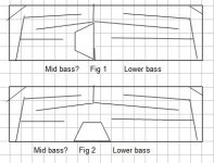
This drawing explains what I was asking a little better. Two figures: One would be used to supplement the lower frequencies - one side lower than the other. I think the Bose cannon does something like this.
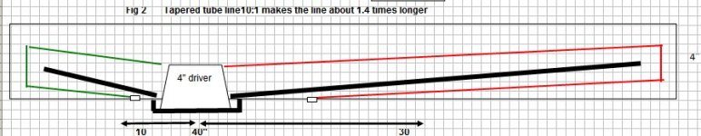
Figure two: I doubt if this would work for a full range as I have never seen a T-line enclosure like it but it might be an interesting trial. I could see it being tested easily in a 4" carpet cardboard cylinder with a long and shorter tapered insert to form the two separate T-lines with the driver about 1/3 the way down the cylinder poking out the front. Do you think it has a chance of succeeding?
Figure two: I doubt if this would work for a full range as I have never seen a T-line enclosure like it but it might be an interesting trial. I could see it being tested easily in a 4" carpet cardboard cylinder with a long and shorter tapered insert to form the two separate T-lines with the driver about 1/3 the way down the cylinder poking out the front. Do you think it has a chance of succeeding?
Attachments
Right, here's a detailed design routine I posted back when there was some interest in them for sofa/bed platform subs, including the late DJK's 'half square' antenna theory in the design for a smoother pipe response: Acoustic wave canon
The second one looks like a weird inverse tapered offset driver TL [TQWT] assuming the vents are out at each end, so makes more sense to me to seal them up and make it a ROAR alignment: Martinsson's Blog - ROAR18
These two are only suitable for lower mid-bass on down.
For wide range/'FR' drivers, I don't see how it can work well as presented with the driver's output being in the 'slipstream' of both pipes unless done like an experiment I did where I divided a 12" dia. cardboard tube in half and cut off the lower half of one, mounting the driver at the other end with the divider board notched out of course.
GM
Hmm, a compound horn [two separate vented systems] is 8th order whereas a TH is 'only' 6th order since it folds back on itself to only one terminus/vent, so not enough info to say for sure which it is.
GM
Shouldn't post when so tired
 Really wish we had permanent edit available! Anyway, the vents combine outside a compound horn, so technically 6th order. Sorry 'bout that!
GM
'Experts' don't make rookie mistakes, so I only claim to be an advanced DIYer. Yeah, but memory's so bad now I don't remember. Oh well, at least I remembered I had a 'senior moment' while answering on another forum and remembered where I posted it, so not quite ready to retire, but getting pretty close.
GM
GM
Based on this desktop near field speaker, I'm going out on a limb here in saying that the idea of using a cylinder is an legitimate and possibly the least expansive way to get a little over an octave of bass where satellites take over..
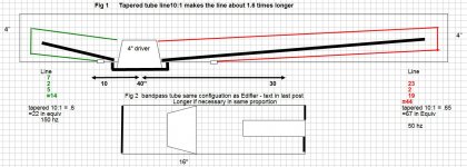
For a trial experiment only, I bought a 26$ system (Edifier) with an amp, two 1" speakers and a 11 inch x 2 inch woofer tube with a cheap 2" driver located 1/3 into a 4th order bandpass channel with a 1/2" x 3" port out of the larger chamber end. I mothballed all but the tube/driver for the experiment to see the possibilities of using a larger driver in a larger diameter tube.
As close as I can tell, the fs of this 2" driver is around 250hz which makes these figures impressive since there is no EQ added to the spl's at one meter.
80 100 125 160 200
79 85 85 80 79
The same 2" driver ported in a 26cu in enclosure has these figures:
80 100 125 160 200 250
66 72 79 84 89 90
So based on this, I think it is worth the effort to try using a 4" cardboard carpet tube in the layout above, as well as experimenting with the rough drawings a few posts above this one. If it follows the same pattern, my 4" fs=105, might get to 50 hz with sufficient output before it runs out of xmax. If so, then the total cost to get 50Hz will be $3.75 since the tube is free.
To me, getting good audio out of smaller drivers is the fun part of DIYing since I already have two theater systems with 2 15" subs and a sunfire with its 1400 watt amp.
Any ideas to improve on this concept is welcomed.
To continue with my idea above and looking for any feedback:
I think I will have reasonable success with Fig2 based on my last post (Edifier tube) but I would like comments on Fig1 below for a full range tube speaker. Does the layout (loosely based on the Bose cannon) have a chance of succeeding? If so, here's how I would attempt it.
Take a home depot 4" cardboard carpet tube (free).
1. Cut a small end off to use as speaker enclosure and carve it to fit the curvature of the tube .
2. Cut the tube lengthwise in half and cut a speaker hole about 1/4 to 1/3 from the end
3. Glue in separators up to the speaker hole and cut in the ports.
3. Seal the tubes back together and seal the ends
4. Attach the speaker enclosure to the tube.
5. wrap the tube with fabric or vinyl
As an option, what about making the tube shorter and sliding in two other smaller diameter tubes at each end to vary the volume and length?
Attachments
??? I never said/implied using tubes won't work for building [ML] TLs, especially as I've been espousing them when appropriate since I got on-line in '96, first building them in '67 after a one armed DIYer showed me his many cheap/free driver variants, just couldn't/can't equate your description with Fig.2.
Ditto your more recent description, especially where your folded pipe equates to a standard BP4 cab alignment, so look forward to any actual build and some measurements to clarify it as all I really know is that a BP4 can be built using tubes since I built one many decades ago with a cheap Radio Shack 8" woofer as an experiment to see if a simple constant flare [pipe] horn was viable, dubbing it my 'sonic cannon', though didn't use a separate vent to shorten it, just a very long tube [TL] for a behind sofa or along a wall firing into a corner sub woofer app.
The only build details I remember is the front tube was 12 ft long, so ~1130/4/12 = ~23 Hz and measured was around 19 Hz from a ~45 Hz Fs wide range acoustic suspension woofer IIRC. The rear chamber I tuned by ear in room as proper test gear was in the thousands back then. Regardless, the owners where very pleased with its performance once they damped it to 'taste'. XO was 120 Hz/2nd order, the only solid state XO I knew how to build.
Re tube in tube, there's been a number of sub build threads over the years, but no longer have any links as these are passe'/ancient history nowadays, so wondering if you're trying to 'reinvent the wheel' or thought up some new tweak.
Regardless, hope it pans out for you. Me, if I ever build a small one for a near-field app I'm going to try DJK's 1/2 square antenna BWC variant to hang off the back of the desk like he suggested.
GM
Ditto your more recent description, especially where your folded pipe equates to a standard BP4 cab alignment, so look forward to any actual build
The only build details I remember is the front tube was 12 ft long, so ~1130/4/12 = ~23 Hz and measured was around 19 Hz from a ~45 Hz Fs wide range acoustic suspension woofer IIRC. The rear chamber I tuned by ear in room as proper test gear was in the thousands back then. Regardless, the owners where very pleased with its performance once they damped it to 'taste'. XO was 120 Hz/2nd order, the only solid state XO I knew how to build.
Re tube in tube, there's been a number of sub build threads over the years, but no longer have any links as these are passe'/ancient history nowadays, so wondering if you're trying to 'reinvent the wheel' or thought up some new tweak.
Regardless, hope it pans out for you. Me, if I ever build a small one for a near-field app I'm going to try DJK's 1/2 square antenna BWC variant to hang off the back of the desk like he suggested.
GM
Thanks GM for the 1/2 wave length idea (I take it, much like the Acoustic Cannon) which made me think of doing it on a m u c h smaller scale with a terminus twist- see Fig 1. BTW, where do you think the idea of using a cyl came from - you and the so many posts you have done - we all thank you for those!
I'm thinking of experimenting with some smaller drivers for my desktop. This has been a fascinated read on these acoustical cannon posts with such experts, that I think I may trythis, with your help.
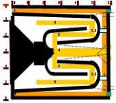
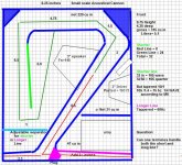
I'm not expecting much from this small enclosure but justd oing it for the kicks as I like to build weird experimental enclosures like this one that has not two but one combined adjustable (pink) terminus using a plug to switch the last part of the line.
I've read MJK's great research and all of these posts but I have some questions if you'll would be so kind to answer: Fig 1
1. Am I correct that the efficiency of a cannon is higher than a BR which is needed for a small enclosure and driver?
2. Adhering to the short line being 1/3 of the long line (1/4 overall) and the idea that a tapered line has a 1.4 longer wave length (MJK), does it work to have both of the lines coming out of the same terminus?
Fig 2.
3. I believe this is more like a double T-Line, if there is such a thing.
4. I would think the problem is, without EQ, that the bass would be weaker because the mid/high would be so much stronger so, lets' assume that we use EQ to attenuate those frequencies. Would it produce a lower and broader bass because of two T-lines?
Any suggestions on either would be appreciated.
thanks
I'm thinking of experimenting with some smaller drivers for my desktop. This has been a fascinated read on these acoustical cannon posts with such experts, that I think I may trythis, with your help.
I'm not expecting much from this small enclosure but justd oing it for the kicks as I like to build weird experimental enclosures like this one that has not two but one combined adjustable (pink) terminus using a plug to switch the last part of the line.
I've read MJK's great research and all of these posts but I have some questions if you'll would be so kind to answer: Fig 1
1. Am I correct that the efficiency of a cannon is higher than a BR which is needed for a small enclosure and driver?
2. Adhering to the short line being 1/3 of the long line (1/4 overall) and the idea that a tapered line has a 1.4 longer wave length (MJK), does it work to have both of the lines coming out of the same terminus?
Fig 2.
3. I believe this is more like a double T-Line, if there is such a thing.
4. I would think the problem is, without EQ, that the bass would be weaker because the mid/high would be so much stronger so, lets' assume that we use EQ to attenuate those frequencies. Would it produce a lower and broader bass because of two T-lines?
Any suggestions on either would be appreciated.
thanks
Attachments
Last edited:
You're welcome!
Yeah, though back in the late '60s/early '70s only knew of Bose due to a coworker buying a 901 system when it first came out and to my ears the best of the series. Actually only learned of the BAWC in more recent times when some DIYers wanted to clone them.
No clue beyond they were being used by local DIYers in the '50s when I got hooked on speaker building, though concrete, terra cotta and asbestos round, rectangular piping was the norm, [surprised I'm not long since dead from all the asbestos dust I inhaled], so really heavy, but made great [mid]bass for the times with the typically high effective Qt tube systems back then.
Right when I was getting serious about learning tower/column [TL} designs in '67, I met a one armed DIYer doing mass quantities of experimenting with small drivers in cardboard mailing, carpet roll tubes, so learned a lot from his/our experiments till he died the next year from long term effects of WWII and Korean War injuries.
The BAWC has greater efficiency only over a narrow BW same as any BP_ alignment that only loads a portion of its usable BW plus its designed with a 2:1 CR to gain back a little of its 'lost' usable gain BW. Not many 'free lunches' in audio system design as you're always trading efficiency for BW.
Hmm, it's been my experience that taper ratio dictates how it affects acoustic path-length, so surprised he's fixed it at 1.4x. Not sure what you're wanting to know: "does it work to have both of the lines coming out of the same terminus?"
You mean a bifurcated terminus TL?
Right, you'll need EQ to flatten it out over it's usable BW if it's not accounted for in the XO's roll-off.
"Would it produce a lower and broader bass because of two T-lines?" If you mean the bifurcated section, no. If you mean the summed response of both sides of the driver, yes with the caveat that one needs to be equidistant from the two pipe ends or position them right next to each other.
I'm having a hard time equating your folding scheme with the simplified layout and AFAIK don't have enough segments to sim it in HR, so have you tried doing one in AkAbak?
GM
First, some days are better than others and today was one of them. Because in my spare time away from my speaker obsession, I refurbish laptops, design and program educational software for my son's school (200 laptops to date.) Anyway, I dropped off 20 older ones at at recylcer and traded them for 20 new Logitech 8 inch woofers that go in THX certified z-2300 systems - free. Amazing what you can find at a electronic recycler. As if I need them to go along with my other 153 drivers lying around.
Back to the post: What is BAWC? I too have a home depot carpet tube with a 3" 1/3 of the way in a 16" total length, closed at both ends with a port in the 12" section. It has powerful near field one octave bass 65 to 120.
I put MJK's 10:1 tapered tables into excel from 20 to 70hz, and compared them to standard quarter wave lengths and they centered around about 1.4 longer (or .71 times the quarter wave length, ie 50 hz = 68 inches but tapered you can get away with 48 inches but with a little less SPL.
Bifurcated terminus and broader bass: What I'm really asking is this: According to my drawing, I only have one terminus with both the short line (1/3 of the longer line) and the longer line coming out the same terminus. Will that work? I base the two line concept on the Bose cannon (acoustical cannon) which has two opened ends with a speaker at 1/4 of the length. This gives two bass bumps. But if you want to make a U shape fold with the terminus at the U ends, then I think the standard protocol is to have the two terminus 1/8 of the longer pipe's wavelength apart. Which won't work for a smaller desktop near field speaker. That is why I thought of the design (my fig 1 drawing above) to have both lines come out of the same terminus. If that concept of two lines ending at one terminus is a no starter, then do I gain anything with fig 2 since the two terminus are close to each other.
AKabak - No I haven't and maybe I should but I feel more comfortable in experimenting with the real thing if it has a chance of working - so that really is my question - Does my drawing have a chance of working?
A long winded explanation - I hope it makes sense.
Last edited:
Bose Acoustic Wave Cannon.
So you're saying it's a BP4 [internal driver] or an offset driver MLTL [driver on side of pipe]?
OK, I've empirically concluded that a 1/2 octave higher tuning [2^0.5] for 10:1 CR is close enough, so 'we' agree on at least this one.
Yes, it just means it's either a T-TL [constant taper], T-TQWT [inverse/horn tapered] or TH [positive/horn tapered], making yours a T-TQWT. These do not conform to the BAWC's 1/3-2/3 driver offset design theory, but way different horn theory that can 'close enough' be simmed in HR and why I think you'll be disappointed in its performance as drawn, so........what driver specs are you using? No way to really tell without them.
FWIW, HR now has the most popular alignments as defaults to start with [F7], then use [ctrl+E] to 'slide' your way to a response optimized for your app and if it can't be made to perform good enough, then you can modify the driver specs in the Wizard as required to allow you to hopefully find a 'close enough' real one if cab size is a major limitation.
GM
So you're saying it's a BP4 [internal driver] or an offset driver MLTL [driver on side of pipe]?
OK, I've empirically concluded that a 1/2 octave higher tuning [2^0.5] for 10:1 CR is close enough, so 'we' agree on at least this one
.Yes, it just means it's either a T-TL [constant taper], T-TQWT [inverse/horn tapered] or TH [positive/horn tapered], making yours a T-TQWT. These do not conform to the BAWC's 1/3-2/3 driver offset design theory, but way different horn theory that can 'close enough' be simmed in HR and why I think you'll be disappointed in its performance as drawn, so........what driver specs are you using? No way to really tell without them.
FWIW, HR now has the most popular alignments as defaults to start with [F7], then use [ctrl+E] to 'slide' your way to a response optimized for your app and if it can't be made to perform good enough, then you can modify the driver specs in the Wizard as required to allow you to hopefully find a 'close enough' real one if cab size is a major limitation.
GM
Last edited:
I was offsetting the driver for two reasons but maybe they don't apply - you certainly know more about this than I so I appreciate your comments.
1. T-line = better harmonics, especially on the first one if the driver is offset from 1/4 to 1/3 the total line.
2. BAWC has the same total line ratio 1/4 (or another way to put it = the short line is 1/3 the longer line)
So maybe my drawing is off a little since I used 1/3 vs 1/4. Do you think I should go with 1/4, 1/3 or the middle of the two?
I still have a nagging question: Can one terminus be used for both the short and long line?
Driver specs+ One of the reasons I don't us HR is that I don't believe the inexpensive driver parameters are static so that is why I make the cabinets, ports and line lengths adjustable to compensate. Plus, I design my cabinets for "drop in" T-lines and DCR configurations. The three different drives I'm going to experiment with are: a 4inch with a published fs of 104 (qts = ?, 3" Fe83 at 122, vas=.9 L, Qts=.64, and a 3" with a high Qts of 1.3, fS=175 and vas=??)
Assuming you were going to experiment with my drawing to use one terminus (if you think it might work, if not then two terminus), what would you change to get me off on the right foot? Remember it is an experiment and that doesn't bother me if the end result is not any better that a BR design.
Thanks again for the comments.
Correct, the BAWC is a variation of an offset driver [tapped] parallel 6th order TL [T-TL].
Again, I said it can/will work and quite well as proven by how it's been so quickly adopted by the prosound community, which is well known for its 'if it ain't broke, don't fix it' mentality when it comes to speaker design; only it will be what we here refer to as a tapped inverse tapered TQWT [T-TQWT], which requires a totally different design routine, etc., as I previously posted, though in retrospect I should have posted an example to show what it will look like in HR's schematic as a single fold, especially if you're determined to empirically arrive at it as you may die of old age first since it's not an intuitive looking design unless well versed in compression horn design theory and even then there's quite a few folks that only know how to 'slide' their way to a good performing alignment whether it's technically correct or not.
The 1st attachment is HR's basic single fold, three segment schematic. The 2nd is an HR T-TQWT [unfolded] complete design details with schematic where you'll notice that the most obvious difference is where the driver's tapped points are Vs yours. That said, input yours as best you can as a reference. Note too that when built as a typical rectangular box with straight board dividers to approximate the flare factor it's always parabolic:
https://i.pinimg.com/originals/ea/c4/f6/eac4f65e049fe35c5cb05a6b719d9b0b.jpg
http://www.diyaudio.com/forums/atta...rn-dayton_rss210ho-8_bw-22-5-150hz_t-tqwt-jpg
All that said, with high Qts' drivers, inverse tapered TQWTs are best suited for alignments where the driver's [low] Vas, Qts' [< ~0.312] dictates a very long vent once big enough to have a low vent mach [< ~ 5% = ~17 m/s], so with your driver choices will need significant stuffing to flatten out its response, ergo ideally should be a horn flare and any with > 1.0 Qts' ideally needs to be a simple constant taper pipe designed using a pipe tuning = Fs/Qts' + heavy damping, which results in a ~damped IB alignment in a smaller, yet still relatively large, cab.
Qts' = Qts + any added series resistance: mh-audio.nl - Home
GM
Again, thanks for your knowledge. As mentioned, I have several of the 8" long throw (11mm) logitech woofers that are used in their Z-2300 model. If you want one and pay for the shipping (about 6 lbs), I would be happy to send you one.
Even though I may die of old age, I like to design and experiment more than I like to listen to music and that is why I would like to try this design of two lines with one terminus. I'm not worried about the drivers, since I have so many that I can try to get the best response. I'm building the cabinet frame for fast "drop in" of the T-line complete interior walls as one unit with foam on the top and bottom of each wall. I will also have a DCR drop in as well as comparing the response with no drop ins, just either sealed or BR. I will publish my findings.
So with that experiment in mind, and not thinking of changing the idea, what ideas/changes would you make to my drawing to give it the best chance of success even though it might fail?
Thanks again
Thanks for the offer, but have no foreseeable use for it, though some folks have used them in compact BP, THs with great success, so might want to offer them to the forum.
I've already posted a lot of info to work with and what IME is a major specific for good-excellent performance, but you keep coming back with a particular mindset, so at this point going to bow out and let you learn it your way [the same way I learned much of it long before personal computers, etc. were available to the masses] and look forward to what you learn/wind up with.
GM
- Status
- This old topic is closed. If you want to reopen this topic, contact a moderator using the "Report Post" button.
- Home
- Loudspeakers
- Full Range
- Does this compact T-Line make sense?