Since you have the miniDSP, why not do a broad notch to bring the 800Hz to 6kHz down?
Here's the Harsch XO thread and how to do it using miniDSP.
S. Harsch XO
1. Set the low pass filter for the woofer as a 4th order Butterworth at central frequency, fc for the XO centerpoint.
2. Set the high pass filter for the tweeter as a 2nd order Bessel at fc.
3. Set the delay of the tweeter equal to 1/2 of the period of one cycle at fc.
4. Use all positive phase on woofer and tweeter.
I have just been fiddling and this EQ setup seems to bring the mid-range under control. It also made the top end a bit bright so I brought that down with a shelf by 1db or so. Thanks for the suggestion, is this what you had in mind?
Also, is my crossover point too low for the Harsch XO to work? The MiniDSP won't support a delay of 22ms as I believe half of 90hz is?
It's a little worrying for me that I have had to apply such heavy EQ to tame these drivers. Am I doing or have done something so very very wrong? I'm a bit of an anxious type so this is going to play on my mind! It's all part of the process I guess!
Attachments
grahamgraham,
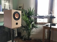
Congrats on an awesome build; the speakers look fantastic.
Regarding the close measurement, I think 15mm is too close for the high frequencies. 80mm (driver diameter) will start to paint a decent picture of the top end, but you might want to try a distance of 185mm. This would put you in the farfield of the frequencies at the top of the spectrum (assuming the entire cone emits high frequencies), and give more consistent results. However, you'll want to position the speakers so the drivers are as far as possible from reflective surfaces. If you can, use the impulse view in REW to determine where the first reflection occurs, and then apply a Hann window with a right hand window length that pushes that reflection down to (or below) -48dB (a good compromise in my experience between reducing ripple and maximizing window length).
A good quasi-anechoic measurement of your speakers would require 3 measurements (the farthest of which would be equal to the baffle diagonal), a lot of tedious post-processing, and difficult to impossible unless you have a huge space or can measure outdoors.
Regarding "omni" measurement mics, I have the Dayton, and 90 deg differs from 0 deg by about 7dB at 20kHz.
Historically, the 'name of the game' is to solve as many acoustic problems as you can before resorting to electronics.
GM
Yes, before I got in to Hifi I produced music and was taught never to EQ the sound system if you could adjust the room first. When I got the MiniDSP I had the intention of only using it to weak my subwoofers but it is coming in handy for this for sure.
grahamgraham,
Congrats on an awesome build; the speakers look fantastic.
Regarding the close measurement, I think 15mm is too close for the high frequencies. 80mm (driver diameter) will start to paint a decent picture of the top end, but you might want to try a distance of 185mm. This would put you in the farfield of the frequencies at the top of the spectrum (assuming the entire cone emits high frequencies), and give more consistent results. However, you'll want to position the speakers so the drivers are as far as possible from reflective surfaces. If you can, use the impulse view in REW to determine where the first reflection occurs, and then apply a Hann window with a right hand window length that pushes that reflection down to (or below) -48dB (a good compromise in my experience between reducing ripple and maximizing window length).
A good quasi-anechoic measurement of your speakers would require 3 measurements (the farthest of which would be equal to the baffle diagonal), a lot of tedious post-processing, and difficult to impossible unless you have a huge space or can measure outdoors.
Regarding "omni" measurement mics, I have the Dayton, and 90 deg differs from 0 deg by about 7dB at 20kHz.
Thank you and thanks for your input also!
Interesting, I have a yard I can use to set up the measurement rig. Though, I am not sure I would be able to get high enough or far enough away from my house to irradiate any boundary interference.
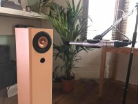
I will definitely try your suggestion of 185mm, thanks. Should I be pointing the omni mic at the cone in the way I showed or should I point it upwards at 90 degrees?
Also, just a note: I have 4 Rockwool / mineral fibre panels in my front room. Two 50mm full size panels at side reflection points and two 100mm full sized panels about 2 metres behind my listening position. Could these be employed to help with indoor measurements?
Thanks everyone for your input, this has really got under my skin as it should be such a simple cabinet enlightenment and the incredibly bright mid/ upper mid is confusing to me considering the Alpair family frequency response. Despite my lack of dampening in the Alpair 6.2m cabinets I needed no extra EQ for their FR. So strange!
A 45 degree mic position (mic pointing diagonally up) without the boom might help reduce the chance of reflections from the mic/stand itself when doing (non listening position) speaker measurements. Also, if you don't have good mic calibration files, 45 deg should be a pretty safe bet as far as response goes.
The panels could help make quasi-anechoic measurements possible, but if it's simply listening pleasure that you're after, my 2 cents is that you'll get better results (and with *much* less effort) by just working off of a single listening position measurement of each channel.
BTW, and I'm probably a little bit out of my league here, the ~60Hz dip in the "brown" measurement makes sense to me as a function of the cabinet tuning (the port is taking over for the driver in that range). This is one of the reasons multiple measurements are needed for a single quasi-anechoic measurement. Also, psychoacoustics aside, I don't see the "green" measurement as having so much of a "bright" upper mid response as it does a "recessed" lower mid response. Treble rolloff looks pretty natural for a room measurement.
Graham, If you have not calibrated your mic for 90 degree measurements, I suggest you redo the seating position measurements with the mic pointed straight at the driver as you did for the near field measurement if you want to be able to compare apples to apples.
Even though the omnimic is stated to be omnidirectional, its calibration is done with mic facing straight (horizontal). A 90 degree position (mic pointed up) will thus lead to a falling high frequency response.
Even though the omnimic is stated to be omnidirectional, its calibration is done with mic facing straight (horizontal). A 90 degree position (mic pointed up) will thus lead to a falling high frequency response.
A 45 degree mic position (mic pointing diagonally up) without the boom might help reduce the chance of reflections from the mic/stand itself when doing (non listening position) speaker measurements. Also, if you don't have good mic calibration files, 45 deg should be a pretty safe bet as far as response goes.
The panels could help make quasi-anechoic measurements possible, but if it's simply listening pleasure that you're after, my 2 cents is that you'll get better results (and with *much* less effort) by just working off of a single listening position measurement of each channel.
BTW, and I'm probably a little bit out of my league here, the ~60Hz dip in the "brown" measurement makes sense to me as a function of the cabinet tuning (the port is taking over for the driver in that range). This is one of the reasons multiple measurements are needed for a single quasi-anechoic measurement. Also, psychoacoustics aside, I don't see the "green" measurement as having so much of a "bright" upper mid response as it does a "recessed" lower mid response. Treble rolloff looks pretty natural for a room measurement.
Thanks, I think your right about the lower mid and as Greg suggested the FR appears more like a test baffle response, perhaps why the lower mid is being lost in the room?
I will try the 45 degree measurements, for sure, cheers!
The vent is tuned to mid 70's so to me it doesn't look like that, to me. Greg, thoughts?
Ugggggh, this has got me down today! I was so distracted at work.
I need an action plan. Here's some things I will try.
1. Remove all stuffing and measure in the various ways proposed above. The alignment is so simple it's confusing it measures so differently.
2. Bung the port to see if it measures as a sealed simulation. Making it simpler might help me reverse engineer things.
3. Inspect the cabinets. I highly doubt there are any leaks or structural issues as I made them incredibly robustly.
4. Sulk a bit.
Does anyone think that maybe the vertical bracing effected the port behaviour?
Dave, Scott, Chris... since you are of the few who have heard these drivers or at least their bigger brothers, what are your thoughts on my situation?
As ever this is a great learning process and is great to have input from all. I'm sure it'll end well... hehe
Graham, If you have not calibrated your mic for 90 degree measurements, I suggest you redo the seating position measurements with the mic pointed straight at the driver as you did for the near field measurement if you want to be able to compare apples to apples.
Even though the omnimic is stated to be omnidirectional, its calibration is done with mic facing straight (horizontal). A 90 degree position (mic pointed up) will thus lead to a falling high frequency response.
Good advice re the apples. Cheers man!
Dave, Scott, Chris... since you are of the few who have heard these drivers or at least their bigger brothers, what are your thoughts on my situation?
Don’t get anal about what the measurements say. Sit down and enjoy them.
Dealing with high end is often best done with off-axis placement. So play with position.
dave
Thanks, Dave. I agree but the measurements have helped me realise the real world shortcomings so far. I wondered if you noted any brightness on the A11MS or the need for EQ correction?
I played about with facing them straight on last night but I found the imaging unfocused. Everyone's hearing is different huh?!
Any thoughts on why the cabinet doesn't act as the simulation suggests it should?
I played about with facing them straight on last night but I found the imaging unfocused. Everyone's hearing is different huh?!
Any thoughts on why the cabinet doesn't act as the simulation suggests it should?
Don’t get anal about what the measurements say. Sit down and enjoy them.
Dealing with high end is often best done with off-axis placement. So play with position.
dave
Don’t get anal about what the measurements say.
dave
I know more than a few people who would disagree with that comment, and not just in audio!
I played about with facing them straight on last night but I found the imaging unfocused. Everyone's hearing is different huh?!
Any thoughts on why the cabinet doesn't act as the simulation suggests it should?
Generally speaking and assuming that the speakers were firing pretty much directly on axis at a 'live' wall parallel to the 'sound' wall as you imply, then for sure it's going to make a mess of any stereo effect, so normally one toes in the speakers to cross somewhere in front of the LP and more often than not with 'ring on axis speakers' [all available 'wide range/FR' drivers] this is typically < 1.0 ft in of one's face, though ones that have it in the extreme [Lowther, Jordan, etc.] often need more distance.
At the extremes where for instance speakers are too far apart relative to the LP can benefit from firing them into the sound wall at the angle required to get the desired pattern at the LP.
The goal here is to try and keep as many room reflections to behind the various listening ears. Maybe 'kill two birds with one stone' at least initially is to find the optimum toe in by ear, then measure each individually and in stereo at the listening position in both planes rather than on axis.
I take it you still haven't ruled out/determined if the cab's damping is the problem......
GM
Last edited:
Generally speaking and assuming that the speakers were firing pretty much directly on axis at a 'live' wall parallel to the 'sound' wall as you imply, then for sure it's going to make a mess of any stereo effect, so normally one toes in the speakers to cross somewhere in front of the LP and more often than not with 'ring on axis speakers' [all available 'wide range/FR' drivers] this is typically < 1.0 ft in of one's face, though ones that have it in the extreme [Lowther, Jordan, etc.] often need more distance.
At the extremes where for instance speakers are too far apart relative to the LP can benefit from firing them into the sound wall at the angle required to get the desired pattern at the LP.
The goal here is to try and keep as many room reflections to behind the various listening ears. Maybe 'kill two birds with one stone' at least initially is to find the optimum toe in by ear, then measure each individually and in stereo at the listening position in both planes rather than on axis.
I take it you still haven't ruled out/determined if the cab's damping is the problem......
GM
I've always toed speakers in since working in production. My personal optimum for most speakers is the triangle meeting just behind my head but I have found with the alpairs that a slightly wider toe works best for imaging.
Hopefully I will be up early tomorrow to measure outside and as high and far away from be house possible. I'll be measuring:
Current stuffing
No stuffing
Incremental stuffing (depending on the no stuffing result)
If I have time before I am dragged out the house by the other half I will be able to try the 45 degree measuring suggestion and maybe on Sunday I can get them back in my LP for some real world measuring! Wish me luck!!
Interesing. I only have a few minutes, but a couple of thoughts, for whatever they're worth.
-The nearfield measurement taken actually corrolates quite well with the data sheet, once the differing graph scales & conditions are accounted for. Attached is an overlay I stuck into PCD7 with the published response & the nearfield taken; I've tweaked the amplitude of the latter as it evidently wasn't calibrated to be equivalent to a 1m standard. The main difference is in the HF, and with an omnidirectional mic. which isn't calibrated or at least not fully so, you'd expect some variation between that & one taken in a chamber with different gear. The LF notch indicated is presumably a box tuning effect; no real surprises there.
-The listening position measures shown in the thread aren't especially unusual (or don't look particularly so to me) given what rooms can do to a response curve & the usual caveats re varying conditions, equipment &c. Per the above, I wouldn't call them 'bright' given that you've got a decline in the HF; it looks like a rise due to the broadband suckout from c. 130Hz - 750Hz (give or take). The loss of the top end proper is presumably due to the mic. positioning / technique used for measuring.
-I haven't had time to read all the thread, but if this is GM's cabinet alignment it seems to be functioning as intended with a rising response in the upper - midbass & damped below, albeit with some room gain kicking in; how much shown depending on space & details of measurement equipment / technique.
Attachments
Last edited:
Thanks for your time, Scott. Most appreciated.
Yes, I am rather chuffed with the similarity to the factory measurements, something must be right, eh, Greg!?
The "broadband suckout from c. 130Hz - 750Hz" is a room issue I now understand. I need to work out a way to fix it but I'm concerned about too heavy EQ settings. The story continues...
Yes, I am rather chuffed with the similarity to the factory measurements, something must be right, eh, Greg!?
The "broadband suckout from c. 130Hz - 750Hz" is a room issue I now understand. I need to work out a way to fix it but I'm concerned about too heavy EQ settings. The story continues...
Interesing. I only have a few minutes, but a couple of thoughts, for whatever they're worth.
-The nearfield measurement taken actually corrolates quite well with the data sheet, once the differing graph scales & conditions are accounted for. Attached is an overlay I stuck into PCD7 with the published response & the nearfield taken; I've tweaked the amplitude of the latter as it evidently wasn't calibrated to be equivalent to a 1m standard. The main difference is in the HF, and with an omnidirectional mic. which isn't calibrated or at least not fully so, you'd expect some variation between that & one taken in a chamber with different gear. The LF notch indicated is presumably a box tuning effect; no real surprises there.
-The listening position measures shown in the thread aren't especially unusual (or don't look particularly so to me) given what rooms can do to a response curve & the usual caveats re varying conditions, equipment &c. Per the above, I wouldn't call them 'bright' given that you've got a decline in the HF; it looks like a rise due to the broadband suckout from c. 130Hz - 750Hz (give or take). The loss of the top end proper is presumably due to the mic. positioning / technique used for measuring.
-I haven't had time to read all the thread, but if this is GM's cabinet alignment it seems to be functioning as intended with a rising response in the upper - midbass & damped below, albeit with some room gain kicking in; how much shown depending on space & details of measurement equipment / technique.
Right! After waiting for a very thorough, noisy and frankly annoying street sweeper and his robotic sweeping van to finish his work this morning, I have finally done some measurements that lead to conclusions!
(It was too windy to measure outside but I am confident of the results)
So...
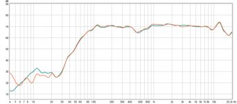
Measured at 185mm on axis.
Orange is the prototype cab with thick stuffing.
Teal is my finished cab with slightly lighter stuffing as per recommendation from Greg.

I can safely conclude the cabinets are working as intended but for the hump that showed in the simulation at 200hz. This is not an issue however as it is perfect for the intended purpose.
There is so little difference between measurements of the cabs that I can only assume the minute variations are slight measuring differences.
The null assumed to be port behaviour was a room mode as I suspected as I moved the measurement area a little further away from the wall.
HOOORAHHHHH!!!!!
Now, to the room measurements...
(It was too windy to measure outside but I am confident of the results)
So...
Measured at 185mm on axis.
Orange is the prototype cab with thick stuffing.
Teal is my finished cab with slightly lighter stuffing as per recommendation from Greg.
I can safely conclude the cabinets are working as intended but for the hump that showed in the simulation at 200hz. This is not an issue however as it is perfect for the intended purpose.
There is so little difference between measurements of the cabs that I can only assume the minute variations are slight measuring differences.
The null assumed to be port behaviour was a room mode as I suspected as I moved the measurement area a little further away from the wall.
HOOORAHHHHH!!!!!
Now, to the room measurements...
Attachments
Righty ho, some room measurements have been done.
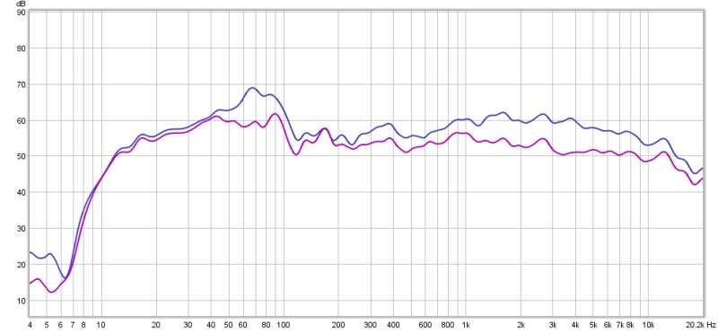
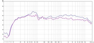
I measured on axis at listening position for each channel and analysed etc. and and the graph below is the L+R averaged to show the overall difference:
I feel I cheated a bit by using REW to output correction files. They took some tweaking as some of the filters really sucked the life out of the FR. But after dialing back and adjusting I feel I got a much nicer response.
Blue is before EQing.
Purple is after EQing.
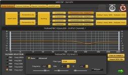
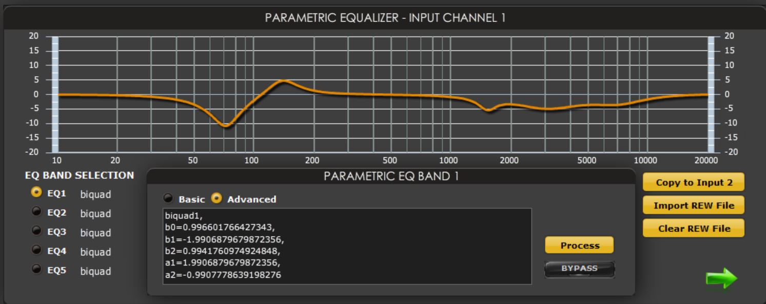
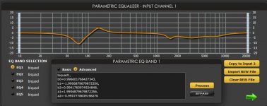
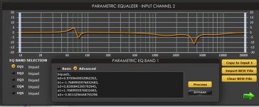
...and these are the left and right EQ applications that have been created in REW.
L
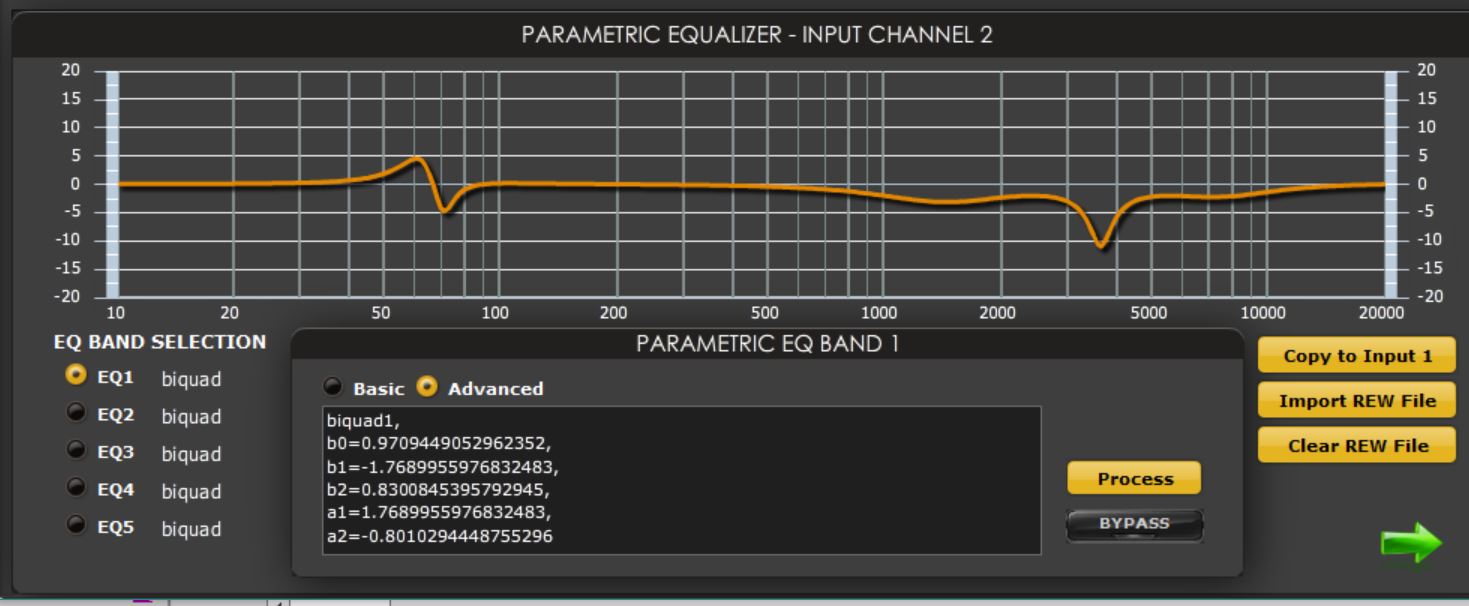
R
The massive adjustments makes me a little twitchy but it does sound very good. Some slight mismatch in FR between the two speakers but I am adjusting minutely every now and then.
Note that the 1500hz-5000hz range as been attenuated quite nicely.
The reason I said I cheated a bit is because I kinda wanted to figure it all out myself but I guess I'm trying to be too much of a smart **** at this point in my understanding of acoustics etc.
I measured on axis at listening position for each channel and analysed etc. and and the graph below is the L+R averaged to show the overall difference:
I feel I cheated a bit by using REW to output correction files. They took some tweaking as some of the filters really sucked the life out of the FR. But after dialing back and adjusting I feel I got a much nicer response.
Blue is before EQing.
Purple is after EQing.
...and these are the left and right EQ applications that have been created in REW.
L
R
The massive adjustments makes me a little twitchy but it does sound very good. Some slight mismatch in FR between the two speakers but I am adjusting minutely every now and then.
Note that the 1500hz-5000hz range as been attenuated quite nicely.
The reason I said I cheated a bit is because I kinda wanted to figure it all out myself but I guess I'm trying to be too much of a smart **** at this point in my understanding of acoustics etc.
Attachments
Last edited:
- Status
- This old topic is closed. If you want to reopen this topic, contact a moderator using the "Report Post" button.
- Home
- Loudspeakers
- Full Range
- MLTL Floorstanders for Alpair 7MS