Here is an unprecedented speaker project that enables one to begin experiencing the purity of current drive easier than before and suits also for those who would rather continue with their existing transistor amplifier. The speaker uses an ordinary mid-woofer as a full-range unit and is driven by a normal low-output-impedance voltage amplifier. The sensitivity loss caused by the series resistors used for the V/I conversion is largely compensated by a step-up transformer. The bass resonance damping necessary in the current-mode is accomplished by a closed mini transmission line and adjusted by positioning of wadding.
The driver is the 8-ohm version of the Scan-Speak model that was included in the current control / voltage control distortion comparison study and in which the modulation distortion on pure current drive dropped by over 30 dB.
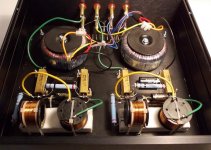
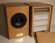
Below are found the circuit and pictures of the adapter unit, containing the electrical components, and of the speaker itself, the other with the back lid opened.
Detailed description of the project
The driver is the 8-ohm version of the Scan-Speak model that was included in the current control / voltage control distortion comparison study and in which the modulation distortion on pure current drive dropped by over 30 dB.
Below are found the circuit and pictures of the adapter unit, containing the electrical components, and of the speaker itself, the other with the back lid opened.
Detailed description of the project
Attachments
Last edited:
If/when the speaker has an impedance of 8 ohms, the impedance presented at the 12+12V side of the transformers is 0.348 ohms. The network feeding that low an impedance will have a *very* low efficiency. Unprecedented, but for the wrong reason I think.The sensitivity loss caused by the series resistors used for the V/I conversion is largely compensated by a step-up transformer.
The sensitivity loss caused by the series resistors used for the V/I conversion is largely compensated by a step-up transformer.
Losses caused by a resistor in a speaker level filter are lost forever as heat. You cannot get this back via a step-up transformer. So I don’t understand where the gain in sensitivity comes from. The concept is interesting, and perhaps one can make the same V-to-I converter at the line-level stage and get a voltage amplifier to act as if it were ancurrent based amplifier? This will use smaller less costly parts, won’t need “big iron” transformers or air core coils or power resistors. You can simply drive the filter with more power from the preamp to make up for the loss in sensitivity. Same concept as PLL XO’s.
So how does it sound?
I was under the impression that the 15w/8434 was about done by 5KHz. 9KHz if you run it wide open & ignore the HF resonance, which, since it isn't designed for such purposes, isn't optimised for operating use. Nice small inexpensive midbass, albeit one that doesn't get very low, with a reasonable operating BW for those purposes, but it's not got sufficient at the top end (especially off-axis) to be ideal as a wideband unit in my book. Still, if you're happy, that's what counts & it's good to see something different.
This is a principle where by trading a few decibels of sensitivity one can achieve a crucial reduction in the most detrimental midrange distortions and almost get rid of the vague EMF:s (motional and inductive) in the signal path. If this is a wrong reason, then of course our interests do not meet.Circlotron said:If/when the speaker has an impedance of 8 ohms, the impedance presented at the 12+12V side of the transformers is 0.348 ohms. The network feeding that low an impedance will have a *very* low efficiency. Unprecedented, but for the wrong reason I think.
(The presented image of 8 ohms is actually 0.42 ohms, as calculated from the real turns ratio instead of nominal voltages.)
Maybe it's time to update such notions.Circlotron said:I think current drive only has a place for a woofer in a sealed box with motional feedback.
Perhaps I was too brief in my description. It is essential here to know the point of reference, which is a situation where the speaker sees the same driving impedance (72 ohms in this case) but without a transformer. So, with a bare 72 ohms series impedance for the 8-ohm speaker, the loss in (voltage) sensitivity will be 20 dB, compared with direct connection. With the transformer, however, one can easily get 20 times more current from the amplifier (80 ohms ---> 4 ohms) while keeping the same 9:1 series impedance to load impedance ratio. Thus, the power drawn from the amp is twice that in the direct connection, and, as again 1/10 of it goes to the speaker, it gets 1/5 of the direct feed power, meaning only 7 dB loss. The gain of using the transformer is thus 13 dB and could be even more if one allowed the amp to see less than 4 ohms.xrk971 said:Losses caused by a resistor in a speaker level filter are lost forever as heat. You cannot get this back via a step-up transformer. So I don’t understand where the gain in sensitivity comes from.
Also, due to some additional gain from the bass resonance and the transmission line, there is less need for baffle step compensation, which gives yet a couple of dB more, so that the final loss in voltage sensitivity is just about 5 dB. Further, if the series impedance were reduced to e.g. 5x (which is yet very useful), instead of the 9x, yet another couple of dB would be saved.
It would need a current feedback loop around the power amplifier. Quite possible but difficult to make it universally stable, as the HF responses of amplifiers vary widely. Passive line level (RC) filtering cannot quite track the usual speaker impedance shapes. (Btw, PLL XO usually stands for phase-locked loop crystal oscillatorxrk971 said:The concept is interesting, and perhaps one can make the same V-to-I converter at the line-level stage and get a voltage amplifier to act as if it were ancurrent based amplifier? This will use smaller less costly parts, won’t need “big iron” transformers or air core coils or power resistors. You can simply drive the filter with more power from the preamp to make up for the loss in sensitivity. Same concept as PLL XO’s.
So how does it sound?
") )
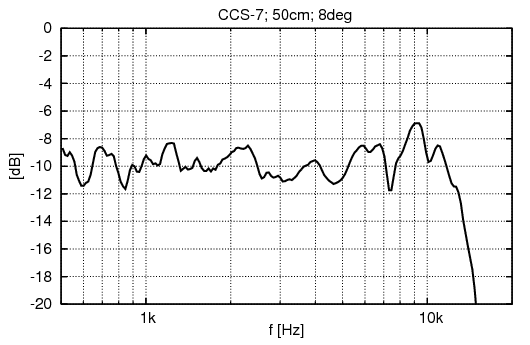
)One additional benefit in current drive is just that the HF range extends naturally higher when the inductance is no more limiting it. Here, for instance, we reach 14 kHz with ease. Thus, one can often do without sophisticated FR drivers, and demonstrating that was also part of the exercise.Scottmoose said:I was under the impression that the 15w/8434 was about done by 5KHz. 9KHz if you run it wide open & ignore the HF resonance, which, since it isn't designed for such purposes, isn't optimised for operating use. Nice small inexpensive midbass, albeit one that doesn't get very low, with a reasonable operating BW for those purposes, but it's not got sufficient at the top end (especially off-axis) to be ideal as a wideband unit in my book.
Below the mid-to-high response, that is already 8 deg off-axis (upward).
The 5" Faitalpro mid woofer is really flat to about 6Khz. I am thinking of using this as a reflecting ( top rear mounted ) driver in my towers.
you could put the transformer in series with the woofer and use the primary ( 115v ) outputs to tailor the load. 20w 1- 3k resistors and .1 to 1uf 400v capacitors
you could put the transformer in series with the woofer and use the primary ( 115v ) outputs to tailor the load. 20w 1- 3k resistors and .1 to 1uf 400v capacitors
Sensitivity has nothing to do with efficiency or, in other words, doesn't tell you how much power you are using to reach a certain SPL. Efficiency does.Losses caused by a resistor in a speaker level filter are lost forever as heat. You cannot get this back via a step-up transformer. So I don’t understand where the gain in sensitivity comes from.
With a common low Zout amp you measure the FR of a loudspeaker at constant 2.83V but that doesn't tell how much power you are using because the impedance is reactive and variable (i.e. the output current from the amp is variable). With a current amp the current is constant and voltage changes when driving a variable impedance.
Many speaker manufactures sell their speakers as 8 ohm nominal but then one finds that these are more like 4-5 ohm speakers. Why do they continue to define them as 8 ohm? It's because sensitivity is higher and makes them look more efficient but they aren't! It's game over once a classic tube amp is used as sensitivity makes no sense anymore.
It always happens if you don't fully compensate the coil inductance. The off-axis is lifted up as well. It's auto-equalisation due to the inductive load.Interesting given that that rarely happens with current drive. Off axis out to 40 degrees?
Sorry to say but this is just the usual approach of the middle ages. Why don't start from the fact that current drive is different and it works in practice if properly implemented? If you don't like it you can tell after you know for real....In theory. In practice it doesn't always work out so pat.
The (inefficient) speaker + network in this 3D has been made precisely for that: let people try without spending a lot of money.
Of course you are free to withdraw but you should keep such conclusions for yourself because they are very likely wrong.
Ah. And there's me thinking that I owned a First Watt F2 for a while and spent some considerable time working with it, while also having a peculiar habit of designing speakers accounting for amplifier output impedance. It must have been a dream. Silly old middle ages me.
You may wish to refrain from making statements about other people's experience in a given field 'for yourself' before checking exactly what it is. If you had, you would be aware of the above and the fact that I actually rather like current drive in certain conditions. 'Sorry to say' however I did not find the wonderful advantages referred to in extending HF response to be an invariant. The Scan midbass in question here is one I am familiar with having used it several times, and its off-axis behaviour > 4KHz is not fantastic, which is the point I was making, since the cone and suspension were never intended to be used over an extended BW and are not optimised for such use. Since this is of some significance in terms of overall performance & sound quality (unless you are nearfield listening only), I have some reservations about its use in this way. As noted, if the OP is happy with the results though, that's what counts.
You may wish to refrain from making statements about other people's experience in a given field 'for yourself' before checking exactly what it is. If you had, you would be aware of the above and the fact that I actually rather like current drive in certain conditions. 'Sorry to say' however I did not find the wonderful advantages referred to in extending HF response to be an invariant. The Scan midbass in question here is one I am familiar with having used it several times, and its off-axis behaviour > 4KHz is not fantastic, which is the point I was making, since the cone and suspension were never intended to be used over an extended BW and are not optimised for such use. Since this is of some significance in terms of overall performance & sound quality (unless you are nearfield listening only), I have some reservations about its use in this way. As noted, if the OP is happy with the results though, that's what counts.
Last edited:
Hi,
Thanks for sharing this.
I don't have knowledge to understand what it is all about, but still, i'm curious, and this offer a way to try something different. In a current project, 4 way active crossed, the mid way 4" got 8db power margin. Should give a try, since it only need few passive component.
Akabak should help simulate this circuit. I've looked at manual, and it seems transformer can be simulated,. I'll give a try when i get time and motivation.
Simulation won't tell anything about distortion, but it should be useful to tweak and see for time integration with the other ways.
I have owned current amps and dedicated speakers that really worked as intended. No tricks. They have been produced for about 30 years. A few years ago the company closed down. The only problem with them was the cost. When I moved to the UK I sold them to friend of mines that still uses them and occasionally I can still listen to them. I know the First watt in "current mode" and, in comparison, is poor.Ah. And there's me thinking that I owned a First Watt F2 for a while and spent some considerable time working with it, while also having a peculiar habit of designing speakers accounting for amplifier output impedance. It must have been a dream. Silly old middle ages me.
You may wish to refrain from making statements about other people's experience in a given field 'for yourself' before checking exactly what it is. If you had, you would be aware of the above and the fact that I actually rather like current drive in certain conditions. 'Sorry to say' however I did not find the wonderful advantages referred to in extending HF response to be an invariant. The Scan midbass in question here is one I am familiar with having used it several times, and its off-axis behaviour > 4KHz is not fantastic, which is the point I was making, since the cone and suspension were never intended to be used over an extended BW and are not optimised for such use. Since this is of some significance in terms of overall performance & sound quality (unless you are nearfield listening only), I have some reservations about its use in this way. As noted, if the OP is happy with the results though, that's what counts.
It's mostly about suspensions. For this reason the new FR might not be an exact "lifted up" copy. That is only roughly true. Moreover there is much more to it than frequency response....
As you claim experience can you spec it out? Not in numbers but in basic principles.
So is this intended to be used with an average voltage-gain amplifier? I'm trying to figure out the aim of the exercise.
I've thought of using a transformer before on a lower sensitivity woofer to up the system's voltage sensitivity, but I'm not an expert on that and would need direction.
Later,
Wolf
I've thought of using a transformer before on a lower sensitivity woofer to up the system's voltage sensitivity, but I'm not an expert on that and would need direction.
Later,
Wolf
Yes, it's designed for conventional low-impedance amplifiers, to pave the way for getting a taste of the mighty benefits of current-drive without first having to build a current-output amplifier (transconductance amplifier), for which there are few instructions available and even fever commercial products. My site offers some knowledge.wolf_teeth said:So is this intended to be used with an average voltage-gain amplifier? I'm trying to figure out the aim of the exercise.
Hi, naturally the principle is also applicable for individual drivers or groups of drivers in a multiway system, active or passive.papasteack said:Hi,
Thanks for sharing this.
I don't have knowledge to understand what it is all about, but still, i'm curious, and this offer a way to try something different. In a current project, 4 way active crossed, the mid way 4" got 8db power margin. Should give a try, since it only need few passive component.
interesting - so the in-band input impedance of the circuit never drops below ~6 ohms. Is a transformer with 1:2.8 turns ratio good for other drivers? If no correction trap is used, is it better to have additional resistance on the primary rather than in series with the load?
also - is using a higher powered solid state amp, what advantages does this approach present vs a simple series resistor?
also - is using a higher powered solid state amp, what advantages does this approach present vs a simple series resistor?
Last edited:
It does drop to ~4 ohms at low frequencies.freddi said:- so the in-band input impedance of the circuit never drops below ~6 ohms.
With that, an 8-ohm load appears as 1.0 ohms and 4 ohms as 0.5 ohms. Quite in the useful range, but the answer is dependent on the current-drive factor desired.Is a transformer with 1:2.8 turns ratio good for other drivers?
Functionally there is no difference, but I don't recommend the latter because the DC current from the amplifier's offset voltage may use up a big portion of the transformer's flux capacity; and even without the DC, the transformer would operate closer to the saturation region.If no correction trap is used, is it better to have additional resistance on the primary rather than in series with the load?
No other advantages known than the sensitivity restored. (Both also protect the speaker against DC faults.)also - is using a higher powered solid state amp, what advantages does this approach present vs a simple series resistor?
However, if filtering is also used without the transformer, inductance values may become impractically high.
Last edited:
Thanks ( from its index, your book appears extremely thorough - wish I had a more powerful brain and better math skills)
With existing speakers which were developed with ~ constant voltage drive, does the principal work best with sealed boxes and open baffles? Simple simulations show response variances as a speaker's input impedance can vary a lot and voltage divider effect minimal at the peaks.
How about front loaded horn systems which have a sealed back chamber? Are simple single ended pentode amplifiers adequate in distortion characteristics to employ for current drive operation ?
- Status
- This old topic is closed. If you want to reopen this topic, contact a moderator using the "Report Post" button.
- Home
- Loudspeakers
- Full Range
- Introducing: Clean-Current Speaker with Transformer Aid and Closed-Channel Damping