Mastering the math portions is not a requisite for the assimilation of the rest of the subject matter.freddi said:( from its index, your book appears extremely thorough - wish I had a more powerful brain and better math skills)
Yes, and existing reflex cabinets may be turned into sealed by blocking the port and adding more damping material. The bass elevation can then be leveled with an RCL network in parallel with the driver. Tuning of the RCL is not even very critical.With existing speakers which were developed with ~ constant voltage drive, does the principal work best with sealed boxes and open baffles? Simple simulations show response variances as a speaker's input impedance can vary a lot and voltage divider effect minimal at the peaks.
That might be even a good idea if the bass boost due to current drive can be mated with the horn gain in the higher ranges.How about front loaded horn systems which have a sealed back chamber?
Not tried, but I would avoid here anything that distorts or adds its signature, given also the increased power demand.Are simple single ended pentode amplifiers adequate in distortion characteristics to employ for current drive operation ?
A RCL network to compensate the woofer resonance peak will never work properly because the actual fs is a function of the compliance of the suspensions. The compliance itself is not constant and depends excursion (i.e. signal dependent). One can optimise it for large signal but will get bad results for low-mid level or vice versa. Compensation networks for impedance peaks only work for midranges and tweeters.
Anyway, if properly done, the current drive will not cause any problem in the FR of the speaker, including bass reflex. The current amp controls the current in the coil and so it does not leave the driver to its destiny but actually makes it work more linearly. Here is where the quality of the driver stands out!
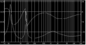
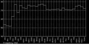
Below I have attached a current driven bass reflex (my old system). As it can been seen, the tiny peak around 80 Hz corresponding to the woofer resonance is nothing in comparison to what room modes do....
Transmission line will be a better choice to reduce the resonance peak without troubles. In fact the bigger brothers of my old speakers were all transmission and double transmission line speakers.
Anyway, if properly done, the current drive will not cause any problem in the FR of the speaker, including bass reflex. The current amp controls the current in the coil and so it does not leave the driver to its destiny but actually makes it work more linearly. Here is where the quality of the driver stands out!
Below I have attached a current driven bass reflex (my old system). As it can been seen, the tiny peak around 80 Hz corresponding to the woofer resonance is nothing in comparison to what room modes do....
Transmission line will be a better choice to reduce the resonance peak without troubles. In fact the bigger brothers of my old speakers were all transmission and double transmission line speakers.
Attachments
The phenomenon is true, and I am also very familiar with it. The strength of the effect also varies much, depending on the rubber material. However, all enclosure principles are more or less sensitive to the fs variation, and I don't see a reason why the closed and RCL-damped current-drive system would be more sensitive to it than an ordinary BR speaker, for instance. Also, in a sealed enclosure, the rather linear air spring helps much to linearize the total spring force and hence to stabilize fs, whereas in a ported system fs is solely on the mercy of the suspension. Therefore I think, if the RCL method cannot work properly due to this, all BR speakers should be considered useless as well, if not for greater reason.45 said:A RCL network to compensate the woofer resonance peak will never work properly because the actual fs is a function of the compliance of the suspensions. The compliance itself is not constant and depends excursion (i.e. signal dependent). One can optimise it for large signal but will get bad results for low-mid level or vice versa. Compensation networks for impedance peaks only work for midranges and tweeters.
The impedance at the peak seems to be 7 times that in the surroundings, so the peak in response will be 17 dB on pure current drive and somewhat less on partial current drive though it may not show up as such in smoothed measurements.45 said:Below I have attached a current driven bass reflex (my old system). As it can been seen, the tiny peak around 80 Hz corresponding to the woofer resonance is nothing in comparison to what room modes do....
What do you mean? That would be true if there were no motor with current control.whereas in a ported system fs is solely on the mercy of the suspension.
In this specific case the resonance is rather high in frequency and woofer has less excursion respect to a sealed box with equal resonance. In a sealed box max excursion happens at the resonance. I generally prefer sealed box but I don't think one is better than the other by default. It depends because there are too many variables and targets.
The reason why those speakers are BR is that this way they can be more efficient. A rather compact 2 ways bookshelf speaker with a 8" woofer and 1" tweeter. The speaker has a true 90 dB efficiency (or sensitivity equal to 93 dB/2.83V being true 4 ohm) also thanks to complete absence of crossover except one capacitor in series with the tweeter to cut power out below its working band. Impossible to do this with sealed box. The same woofer in fact could work very well in sealed box with the classic zero feedback triode amp with 3-5 ohm Zout but the box would be bigger and efficiency would be no more than 87 dB and also requiring a cross-over at least to compensate for the lower efficiency at the lower end. So more likely 86 dB....This also makes excursion at the resonance even lower for the BR at the same SPL in comparison to the SB with same drivers.
Therefore I think, if the RCL method cannot work properly due to this, all BR speakers should be considered useless as well, if not for greater reason.
The only speakers were I have seen the RCL applied to woofer/sub-woofer are actually BR! However the in-air resonance of the driver is rather low around 20Hz, in the cabinet is no more than 50Hz and the driver size is at least 10". Otherwise, regardless of bass alignment, I have only seen it were excursion is not a big fraction of the driver Xmax.
The impedance at the peak seems to be 7 times that in the surroundings, so the peak in response will be 17 dB on pure current drive and somewhat less on partial current drive though it may not show up as such in smoothed measurements.
I am afraid that might be true for an emulation of current amplifier.
The suspension of that woofer is treated foam and the woofer has a compliance around 1.8-1.9 mm/N and with very linear behaviour. Despite the large peak at the resonance the frequency response peak is tiny because it has a powerful motor and the current provided by the amp is amazingly clean. It basically works like a perfect very FAST damped oscillator with no inversions along the impulse response that are the first and most important indicator of distortions and actually make the impulse last longer. It does have overshoot as expected but is not big and response is faster than typical voltage drive. I don't think a 1/3 octave response can smooth a 17 db peak down to 2-3 dB's. That resonance FWHM (full width half maximum) spans approx. from 70 to 90 Hz (so it's about 20Hz wide).If it were really 17 dB I would expect some 8-9 dB smoothed peak.
The amp has 27 Kohm output impedance and can provide up to 18A peak current. The power stage is DC coupled solid state made with custom mosfets, vacuum tube preamplifier/input stage. It started its life as demonstration model, then was sold to a person from whom I bought it. Basically third hand, otherwise would have been too expensive for me to buy....
Last edited:
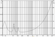
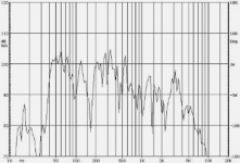
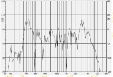
Another example with 8" full-range with whizzer cone. No smoothing here. Very visible the equalising effect of the coil inductance at high frequency. Of course nothing can be done on the midrange peaks and deeps coming from the interaction of the whizzer cone with the main cone....
Here the resonance peak (the one in the middle) is approx. 4x (i.e. 32 ohm vs 8ohm) but there is no 12dB peak. From left to right: impedance, voltage drive, current drive.
Here the resonance peak (the one in the middle) is approx. 4x (i.e. 32 ohm vs 8ohm) but there is no 12dB peak. From left to right: impedance, voltage drive, current drive.
Attachments
Last edited:
A description of the sealed box implementation has now been added at the bottom of the page.
The resonance frequency of the RCL network is here 111 Hz while that of the speaker is about 90 Hz. The component values are also quite applicable at least as a first guess for other 8-ohm speakers with a comparable fs.
The inductance is not yet too high to be realized also on a single laminated bar core since the DC resistance of the coil is unimportant.
Bass resonance management has often been considered as the main challenge on the way to implement current drive with existing high-Qm drivers, that are intended for voltage use. Now there are even alternative ways for that, applicable also in the passive domain; so there is quite no more justification for the ascendancy of voltage drive, at least where provable and obvious purity and fidelity are pursued.
Last edited:
About bass reflex
Driven by voltage or current signal? I just thought it makes a difference.
The only speakers were I have seen the RCL applied to woofer/sub-woofer are actually BR!
Driven by voltage or current signal? I just thought it makes a difference.
The result is non-linear distortion. Drivers which measure with wildly varying T/S parameters versus drive level also inherently cause high distortion with significant excursion even when voltage controlled, so it's kind of a moot point. The drivers I've measured which have very stable T/S parameters versus drive level have low bass distortion.A RCL network to compensate the woofer resonance peak will never work properly because the actual fs is a function of the compliance of the suspensions. The compliance itself is not constant and depends excursion (i.e. signal dependent). One can optimise it for large signal but will get bad results for low-mid level or vice versa.
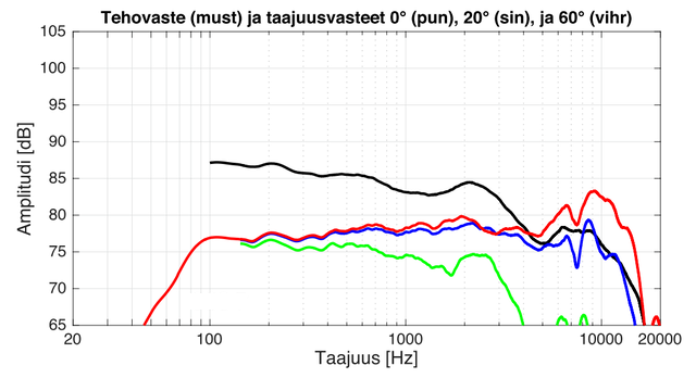
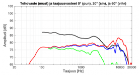
The anechoic response of the speaker with estimated power response has now been taken (red: 0deg, blue: 20deg, green: 60deg, black: power). Quite neat and almost as intended, except perhaps for the elevation at 2+ kHz, the reason for which is not very clear. Anyway, this region can easily be adjusted lower simply by increasing R3 a little. The low-end -6dB cutoff frequency is here slightly higher than the 64 Hz I had estimated. The difference may arise because due to the adapter the driving level remains here lower than usual, and bass corner frequencies always depend a little on the signal level. The on-axis response extends beyond 15 kHz (-6dB) (note: without whizzer cones or specialty drivers), but the best listening direction is somewhat off-axis.
Attachments
Here are found some more of silencing distortion measurements comparing current and voltage control, taken at subwatt levels. Microphone effects have been avoided and the output levels properly matched. The results are quite in line with those of mine.
Nonlinear distortion measurements of loudspeakers - voltage and current control
Nonlinear distortion measurements of loudspeakers - voltage and current control
- Status
- This old topic is closed. If you want to reopen this topic, contact a moderator using the "Report Post" button.
- Home
- Loudspeakers
- Full Range
- Introducing: Clean-Current Speaker with Transformer Aid and Closed-Channel Damping