The front chamber basically acts as a band pass and like all filters and almost all cavities it ofcourse also got a resonance.
The front chamber acts as a low pass filter.
Minimise the chamber depth to reduce the possibility of resonances in the frequency range of interest.
The front chamber acts as a low pass filter.
The front chamber makes the horn a bandpass.
If I calc the cavity resonance of the initial "accidental" feature using f=v/2*pi *( A / V*L)^0.5 I get 2800Hz. It's pretty close considering the cavity is not a simple shape and the cone can move as well.
If it were a low pass or bandpass I would expect a HF rolloff at 3KHz and no recovery. However the FR continues straight through it. So my money is on cavity resonance causing a null.")
If it were a low pass or bandpass I would expect a HF rolloff at 3KHz and no recovery. However the FR continues straight through it. So my money is on cavity resonance causing a null.
You are clearly having way too much fun.
I also messed around a lot with my Fostex FF85WK. I made ridiculously long foamcore TL's (Nagaoka F81 inspired), conical foamcore front horn, back-loaded "horn". I also toyed with holes along the length of the TL, to see if I could de-Q certain resonant modes, but to no avail, it mostly killed all loading and output, as you seem to have found out. I've also made paper petal horns, but for compression drivers though, 11 segments, painstaking assembly!
Keep it up!
Do you have a link to those experiments ? I'm always looking for inspiration
Do you have a link to those experiments ? I'm always looking for inspiration
The old threads are probably hanging around on back pages, but I bet most images are gone from Imageshack doing what Photobucket did more recently. I didn't have a ton of solid data and the premise was often a bit out there - it was mostly goofing off - but I had fun.
Ok, one that I'm tempted to re-visit is a variation of the Nagaoka F-81. This was a design for the Fostex FE83 or FE83e and it's basically a pipe over 12' (!) long. All the Nagaoka designs are fascinating IMO.


It was clearly not designed according to any type of textbook consideration we normally go for - it's just a different way to do things where results probably match with the desires of minimalist Japanese Ultra-Fi enthusiasts.
Anyway, I wanted to inject just a bit of more standard design principles into it. My idea was to set the length so that the 3/4 resonant mode was actually the main output around Fs or so, while the fundamental 1/4 mode would hopefully provide just a bit of loading way down low. The 5/4 mode would be dealt with by placing the driver at 1/5 down the line instead of the typical 1/3 and all upper modes, 7/4+, damped with stuffing. It sounded not too bad with FF85WK at 226cm long. IIRC, this was the speaker I tried to de-Q with small holes, which utterly failed.
I was thinking of trying it with Vifa TC9 if I get a pair, foam-core prototype of course. I think I have the basic design drawn in Illustrator somewhere.
Another thing I wish I'd spent more time on is current drive amplification. I configured a Gainclone amp for this and quickly tested a couple of FR speakers I had, but never properly designed one for it, which is usually quite different. There again, the Vifa TC9 could be a good candidate due to its fairly low Qms and impedance magnitude.
Last edited:

The front chamber makes the horn a bandpass.
Correct, but your original statement was: "The front chamber basically acts as a band pass", which is not correct.
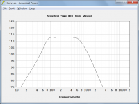
The front chamber acts as a low pass filter. The horn itself acts as a high pass filter. The combination of the two acts as a band pass filter, as shown in the attachment for an exponential horn with a flare cutoff frequency of 70 Hz.
The response of the system will fall off at high frequencies even without a throat chamber, but at a lesser rate, due principally to the combined mass of the driver diaphragm and voice coil, and the voice coil inductance.
Attachments
That is a massive path (12 feet!), and it looks like a rear loaded horn as the path area is expanding. Probably won't repeat that
The simulations are interesting though, assuming some fudge factors. (*) The roll off matches room gain, so if used in a room where room gain starts high enough this would even out quite well.
(*: fudges applied: damping through the entire line to emulate acoustic losses, I shelved the response down some 3 to 6 dB above 200 Hz because I think the driver sees less boundary loading than the hornmouth, I notched the response down at 189 Hz, the half wavelength frequency of the straight sections assuming there is a cancellation there. This yields essentially flat response from the midrange to 20 Hz. I am not saying this holds up in real life, walls aren't perfect boundaries, room modes will screw this up, the drive unit won't be happy when fed with depth charge explosions in submarine movie sound tracks, but at least it reflects some possibilities. It's certainly no worse than many other backloaded horn designs.)
I googled around a bit after seeing the Nagaoka F-81 (again) in this thread and found some interesting remarks by Blumenco and Scottmoose on this little horn-pipe-thing. Blumenstein Audio had a modified version of it, sold as a commercial product. It must have done something right to justify its size and cost beyond a simple sealed box for the drive units used.
BP8 bandpass
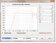
In all the previous tests the one thing that stands out, in both the measurements and listening, is the absence of LF performance. The LF (<150hz) has rising distortion and falling SPL. I was wondering if a different configuration could fix this while still using a PC83-8. After a bunch of HornResp trials I'll settled on a 2 driver BP8 design. Design files added below. It looks like it would be a good addition.
In all the previous tests the one thing that stands out, in both the measurements and listening, is the absence of LF performance. The LF (<150hz) has rising distortion and falling SPL. I was wondering if a different configuration could fix this while still using a PC83-8. After a bunch of HornResp trials I'll settled on a 2 driver BP8 design. Design files added below. It looks like it would be a good addition.
Attachments
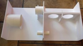
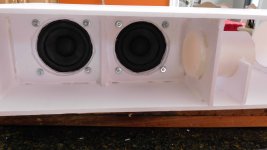
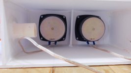
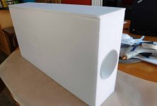
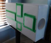
BP8 build
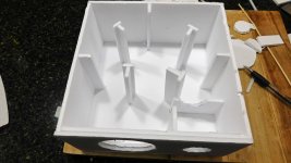
A few pics of the design build, which is more complex than the previous ones. Two drivers were required to get the Sd up to something usable
A few pics of the design build, which is more complex than the previous ones. Two drivers were required to get the Sd up to something usable
Attachments
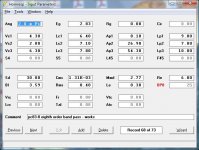
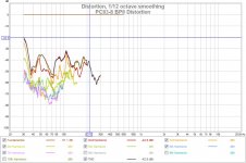
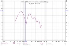
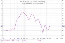
BP8 initial measurements
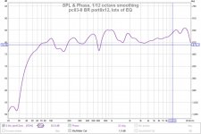
First I have to say, my jaw dropped when I heard what came out of this thing. Real bass from 2 smallish drivers, I tested several times to be sure.
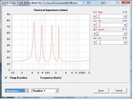
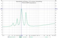
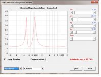
It still has problems that will be addressed, as seen in the impedance graph. I though I would still give it a trial run with these "uneven" peaks. The FR has a nasty 100Hz notch but it produces good bass. More surprising, and what I was after, is the distortion is kept moderate at an avg -35db ref fundamental under 200Hz and down to 45Hz.
First I have to say, my jaw dropped when I heard what came out of this thing. Real bass from 2 smallish drivers
, I tested several times to be sure. It still has problems that will be addressed, as seen in the impedance graph. I though I would still give it a trial run with these "uneven" peaks. The FR has a nasty 100Hz notch but it produces good bass. More surprising, and what I was after, is the distortion is kept moderate at an avg -35db ref fundamental under 200Hz and down to 45Hz.
Attachments
Last edited:
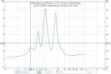
BP8 last try
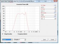
I'm throwing in the towel on this one. I could not get 4 even impedance peaks even after many speaker surgical attempts. This is a very tricky speaker design to tune and I could not get it to behave properly. I tweaked the chamber volumes, filling material, and port lengths.


This is as close as I could get to the HornResp model.
I'm throwing in the towel on this one. I could not get 4 even impedance peaks even after many speaker surgical attempts. This is a very tricky speaker design to tune and I could not get it to behave properly. I tweaked the chamber volumes, filling material, and port lengths.
This is as close as I could get to the HornResp model.
Attachments
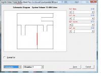
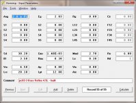
That is a prime example of hornresp not delivering an accurate simulation at ported enclosures. Be it the parameters not properly measured, be it an user error. Looking at the input parameters, the latter is pretty much likely though, that are the parameters of just ONE driver. With two the Sd, Vas, Re and Le changes, the latter two depending on how you wire them. You could take one driver out, close the cutout of it and measure again.
My experience with hornresp has been very good.
If you look at the input page a few posts (#51) back, the design is BP8 with 2S drivers (2 in series). I have also gone back and retried the sim with just a single driver. A BP8 should have 4 impedance peaks that I cannot get in this design. I suspect there is a problem with the foam core flexing in resonant designs. The impedance peaks that I get are lower than expected and the only way I can raise them is by shortening the tuning ports. I think its why the lower peaks are affected more and no tuning can raise them.
If you look at the input page a few posts (#51) back, the design is BP8 with 2S drivers (2 in series). I have also gone back and retried the sim with just a single driver. A BP8 should have 4 impedance peaks that I cannot get in this design. I suspect there is a problem with the foam core flexing in resonant designs. The impedance peaks that I get are lower than expected and the only way I can raise them is by shortening the tuning ports. I think its why the lower peaks are affected more and no tuning can raise them.
Last edited:
That is a prime example of hornresp not delivering an accurate simulation
What do you expect, when the panels of the prototype enclosure in this case are most certainly vibrating / flexing?
Looking at the input parameters, the latter is pretty much likely though, that are the parameters of just ONE driver.
You are obviously not familiar with how Hornresp operates, which makes me wonder just how qualified you are to pass judgement on its performance.
Bass Reflex 4.5L
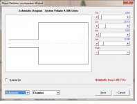
I should have done this as the first foam core resonant design. A simple single chamber bass reflex that is easy to test and tune. This is a test to see if I can stop the walls from flexing enough to get a usable design.
I should have done this as the first foam core resonant design. A simple single chamber bass reflex that is easy to test and tune. This is a test to see if I can stop the walls from flexing enough to get a usable design.
Attachments
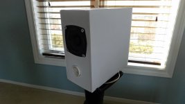
Bass Reflex 4.5L Build
I added several posts to the design to reduce the wall panel flexing (pic#1,#2). This will not stop the wall core from flexing between inner and outer skins that would change its wall impedance.
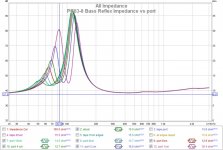
I should have 2 impedance peaks at approx [50Hz, 100Hz] using the hornresp design. What I get is a small bump at 50Hz and a large peak at 110Hz so they are in the right approx place. However, just like in the BP8 case, the low freq (50Hz) impedance peak is too small.
So I tried adjusting the port (8cm^2 x 12cm) length (graph#1) to see if I could find a tuning that worked. Unfortunately, I needed to reduce the port to just the thickness of the foam core opening to get equal impedance peaks. Even more unfortunate, is they occur at higher freq making it unusable for bass extension (graph#2). Lesson learned : wall impedance is important, and foam core is not usable for resonant designs.
I added several posts to the design to reduce the wall panel flexing (pic#1,#2). This will not stop the wall core from flexing between inner and outer skins that would change its wall impedance.
I should have 2 impedance peaks at approx [50Hz, 100Hz] using the hornresp design. What I get is a small bump at 50Hz and a large peak at 110Hz so they are in the right approx place. However, just like in the BP8 case, the low freq (50Hz) impedance peak is too small.
So I tried adjusting the port (8cm^2 x 12cm) length (graph#1) to see if I could find a tuning that worked. Unfortunately, I needed to reduce the port to just the thickness of the foam core opening to get equal impedance peaks. Even more unfortunate, is they occur at higher freq making it unusable for bass extension (graph#2). Lesson learned : wall impedance is important, and foam core is not usable for resonant designs.
Attachments
Last edited:
Bass Reflex 4.5L Build
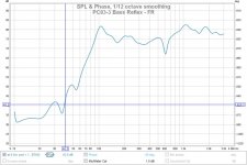
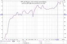
I missed the edit window to add these graphs of the design with the initial 8cm^2 x 12cm port from hornresp. This shows the saggy bass associated with the impedance peak problem due to foam core. It is possible to use this with some EQ to lift the saggy bass but its a lot of EQ (seriously a 20db twist to flatten it). Last of the resonant design foam core trials.
I missed the edit window to add these graphs of the design with the initial 8cm^2 x 12cm port from hornresp. This shows the saggy bass associated with the impedance peak problem due to foam core. It is possible to use this with some EQ to lift the saggy bass but its a lot of EQ (seriously a 20db twist to flatten it). Last of the resonant design foam core trials.
Attachments
Last edited:
- Home
- Loudspeakers
- Full Range
- Dayton PC83-8 (3") test results