I think the low Qts thing is partly mythical.
It is mythical, or at least partly. By itself Q is not a particularly good guide; ultimately if you don't have the raw motor power the driver can 'stall out' (for want of a better phrase, this frosty morn') if asked to drive a large horn, particularly in the HF. But context is always important. People tend to look at the classic drivers with their massive motor strength & forget that a/ they needed it for sheer efficiency, and b/ what was feeding those drivers: either high output impedance, or variable impedance-matching amplifiers.
Last edited:
I guess it's not so much about if a given driver can be horn-loaded in absolute terms, but the frequency range wherein it is useful. I suppose that upper mass corner (2*Fs/Qts) is therefore a better indicator for an intended application?
How would we then compare the horn suitability of two drivers with different specs, but the same mass corner, assuming all else being as equal as can be?
2*50Hz/0.25 =: 400Hz (usual suspect for horn use)
2*100Hz/0.50 =: 400Hz (likely deemed "unsuitable" by Qts alone)
How would we then compare the horn suitability of two drivers with different specs, but the same mass corner, assuming all else being as equal as can be?
2*50Hz/0.25 =: 400Hz (usual suspect for horn use)
2*100Hz/0.50 =: 400Hz (likely deemed "unsuitable" by Qts alone)
I guess it's not so much about if a given driver can be horn-loaded in absolute terms, but the frequency range wherein it is useful. I suppose that upper mass corner (2*Fs/Qts) is therefore a better indicator for an intended application?
I'd certainly take it as more useful than Q alone. Leach took a lot of the fun out of horn design of course (assuming you're aiming for maximum efficiency which isn't always the case. That said, even when you aren't, it's still of value).
How would we then compare the horn suitability of two drivers with different specs, but the same mass corner, assuming all else being as equal as can be?
2*50Hz/0.25 =: 400Hz (usual suspect for horn use)
2*100Hz/0.50 =: 400Hz (likely deemed "unsuitable" by Qts alone)
Not by me (as in deeming it 'unsuitable' by Qt alone) & is in part application specific. Of the two, all other things being equal I'd take the unit with the lower Fs & more motor power. The issue with that is that those other things are rarely equal.
")
The issue with that is that those other things are rarely equal.
Why can't everything just be apples?
url=https://en.wikipedia.org/wiki/Filter_bubble]Filter bubble - Wikipedia[/url]
Some browsers don't do this.
Ah! Good to know! Thanks! What I know about such things would probably fit on the head of a pin
and to think I had the option to be trained by Burroughs back in '64 on all things computer, but seemed way too tedious/boring nor could forsee enough future in it career wise.GM
It is mythical, or at least partly.
I started a response with 'It's all mythical......' then said what you said in my much more 'wordy' way, so +1
.That said, this myth just refuses to die, so time to repost an extreme example I used over a decade ago that by now should be considered valid, what with all the 'proof of concept' of MJK's MathCad worksheets: http://www.diyaudio.com/forums/subwoofers/82694-giant-subwoofer-8.html#post1090936
GM
I guess it's not so much about if a given driver can be horn-loaded in absolute terms, but the frequency range wherein it is useful.
I don't see it.
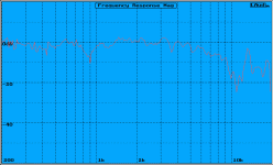
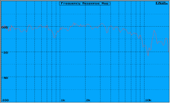
My measurements, in a horn (linked earlier): same Fs, different Qts, same FR plot. The only difference was sensitivity.
Look at the data for field coil drivers (I attached one Supravox example). Same FS, but different voltages change the Qts - without changing the shape of the FR plot.
Look at Martin King's measurements of the DX range of Lowther speakers.
The DX2 and DX3 appear to share the same phase plug and cone, and to differ only in magnet strength. The off-axis graphs are easiest to compare.
Lowther DX2 Driver Measurement Results
Lowther DX2 Driver Measurement Results
Again: different Qts, same useful frequency range.
From these examples, it seems that, where the cone = the same and only the magnet strength changes, there is no real difference on the frequency range wherein a driver is useful.
Are there some good (apples-to-apples) counter examples?
Note: for the last example, Martin King's on-axis measurements show that the lower Qts DX4 driver does gain a few dB on the ragged HF resonances, compared to the 'lesser' drivers.
1) maybe that's the origin of the idea that low Qts = more extended HF. I guess whether this is good for you depends on how much hearing loss you're compensating for.
2) maybe Mr. King didn't use the DX4 in his final build for this reason.
Attachments
Last edited:
i have a pair of yamaha 6115H horns... i know im going to sound like an idiot but here it goes, i used a mackie m1400i amp to try to run them but no go . no sound came out of them is there something im doing wrong ? i didnt turn the volume up too much for fear of damaging them so ... could that be my failure reason ? please help me obi wan kenobi , youre my only hope
I started a response with 'It's all mythical......' then said what you said in my much more 'wordy' way, so +1
You might want to post that after all...
My measurements, in a horn (linked earlier): same Fs, different Qts, same FR plot. The only difference was sensitivity.
If you're primarily measuring in the mass dominated ('flat') BW, i.e above the mass-corner frequency of the driver, then you shouldn't see major differences other than SPL in otherwise identical drivers. In some cases you may get some when the cone is over-driven, but much of this is of primary relevance to the rising response (acceleration) BW below the mass corner & you'd need dramatic changes to get very large shifts otherwise.
1) maybe that's the origin of the idea that low Qts = more extended HF.
I haven't seen that idea raised very often. Good job too, since, unless you take it so very broadly it borders on meaningless in most circumstances. HF extension in a wideband driver is determined by the resonant / flexing behaviour of the cone
2) maybe Mr. King didn't use the DX4 in his final build for this reason.
AFAIK Martin thought the DX4 was the pick of the bunch -enough so that he preferred to use it in another project where he was presumably hoping to extract more performance than could be done with the simple MLTL. MLTLs aren't really ideal for Lowthers, although with appropriate EQ they work fine providing you don't mind the restricted LF dynamic range.
Last edited:
You might want to post that after all...
It's all mythical in that while the drivers were low Qt, their effective Qt was high when coupled to the high output [often, matching] impedance amps used back then, plus at least with high end consumer and prosound apps they may have up to at least an additional 20 ohms of variable damping [tone controls].
Note too, that at least with 'old tech' compression drivers, once coupled to the horn the rear cover can be removed and it ~ only adds dipole 'ripple', i.e. is reactance annulled if on a hyperbolic and nearly so on a hypex horn. Re bass horns, note the heat dissipation vents in the rear covers proving that combined with short horns with large throats have a high system Q [sysQ] even though they're low Qt [high voltage] field coil drivers:
http://www.audioheritage.org/images/lmco/photos/products/shearer/shearer5.jpg
http://www.audioheritage.org/images/lmco/photos/products/shearer/shearer3.jpg
Basically then, you want to design based on the desired effective upper mass corner.
All that said, this myth just refuses to die, so time to repost an extreme example I used over a decade ago that by now should be considered valid, what with all the 'proof of concept' of MJK's MathCad worksheets:
http://www.diyaudio.com/forums/subwoofers/82694-giant-subwoofer-8.html#post1090936
GM
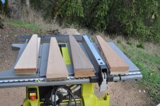
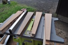
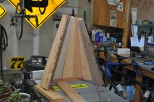
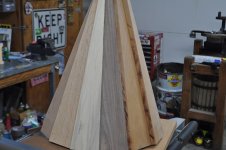
I need more wood. Some pieces were split, some were to narrow and some were sacrificial. I get this free from the local cabinet maker. Attempting 15 sided horns. Size is not of utmost importance at this stage. Diameter is 22", length 19.5". Still, have all my fingers.
Attachments
- Status
- This old topic is closed. If you want to reopen this topic, contact a moderator using the "Report Post" button.
- Home
- Loudspeakers
- Full Range
- Horn Drivers