Hi All,
I am Brazilian and I have hobby to do DIY projects that are documented in my youtube channel (in Portuguese): www.YouTube.com/RenatoBrant
I am designing my first TL. I want to make a project different from everything that exists because I want to make a compact and portable box.
this is my first draft: YouTube
Obviously, because of the size, I'll have to sacrifice some of the sound quality.
For this, I intend to use class d amplifier (which I hate).
I am doing the dimensions calculations manually, but to avoid errors, I would like to purchase Mr. King's Transmission Line Worksheet for MathCAD.
Where to I buy it?
Thanks,
Renato Brant
MJK is here:
Quarter Wavelength Loudspeaker Design
You can also have a look at this one. The project is on halt, but the software is still available.
Transmission Line Modelling Software
Quarter Wavelength Loudspeaker Design
You can also have a look at this one. The project is on halt, but the software is still available.
Transmission Line Modelling Software
Hey X,
Would there be a "sticky" on how to design a MLTL with HornResp? And does it take stuffing density and volume into account?
I tried LeonardAudio TL sim, and I was thoroughly impressed, but the stuffing is not finished and doesn't match "real-world" data.
Otherwise, it looks like it should be MJK.
I have enough stuff to do lately, I'm not in the mood to learn something hard like Akabak!")
Would there be a "sticky" on how to design a MLTL with HornResp? And does it take stuffing density and volume into account?
I tried LeonardAudio TL sim, and I was thoroughly impressed, but the stuffing is not finished and doesn't match "real-world" data.
Otherwise, it looks like it should be MJK.
I have enough stuff to do lately, I'm not in the mood to learn something hard like Akabak!
I don't use HR enough to answer your question - perhaps David McBean, the author of HR can answer. I can post a basic straight TL script for Akabak that anyone can edit and get reasonable answers with. The hard part is installing a legacy Windows XP virtual machine to be able to run it. Or unless you have an old PC handy to do it directly.
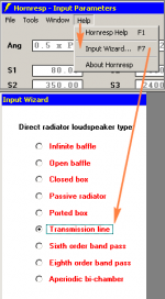
An ML-TL can be modelled quite easily in Hornresp.
This isn't strictly on-topic, but I'm calling it close enough.
Set for Offset Driver.
S1 = area of closed end
S2 = area at the driver
S3 = area at the ported end
S4 = port area
S5 = port area
L12 = distance from closed end of the line to the driver
L23 = distance from driver to ported end
L34 = short, since the port usually happens suddenly
L45 = port length
To the original poster, I'd recommend passive radiators for portable use. They seal the cabinet from dust and allow you to tune the cabinet to any frequency you like without having to fit a lot of bits of wood in there.
Chris
Note that the vent is at the bottom, but for best overall performance needs to be higher up unless the driver is at the extreme top, so use the Wizard's 'acoustical power'/'chamber'/'path' tool to find the optimal location at the listening position [LP] or just put it down at my default ~L*0.84.
GM
GM
An ML-TL can be modelled quite easily in Hornresp.
This isn't strictly on-topic, but I'm calling it close enough.
Set for Offset Driver.
S1 = area of closed end
S2 = area at the driver
S3 = area at the ported end
S4 = port area
S5 = port area
L12 = distance from closed end of the line to the driver
L23 = distance from driver to ported end
L34 = short, since the port usually happens suddenly
L45 = port length
To the original poster, I'd recommend passive radiators for portable use. They seal the cabinet from dust and allow you to tune the cabinet to any frequency you like without having to fit a lot of bits of wood in there.
Chris
Good practice for TL sims, so, I hope close enough to OP's subject.
I tried that "recipe" (and thank you very much for sharing, I think I got it), but it's still off from MJK's simulation of the original TABAQ, and looks more like the LeonardAudio TL sim software, with over damping if I enter the numbers provided with the TABAQ design.
GM, Do I understand your point correctly?
If I am designing a TL with a line length of 40" and a bottom firing port, a vent that stuck 6.4" into the line, would be at a near optimal position?
Is positioning the vent within the line a similar thing to the positioning of the driver within the line? Is there a similar rule of thumb for the driver or best simulated?
Thanks,
-Tom-
Small Passive Radiators
Like this?
Peerless 830878 Peerless 3.5" Mini Passive Radiator
Or this?
Samsung U083L03SSK1 3" Poly Cone Passive Radiator
Like this?
Peerless 830878 Peerless 3.5" Mini Passive Radiator
Or this?
Samsung U083L03SSK1 3" Poly Cone Passive Radiator
Both will do fine.
Remember your PRs need to have roughly 2x the cone area of the main drivers.
Chris
GM, Do I understand your point correctly?
If I am designing a TL with a line length of 40" and a bottom firing port, a vent that stuck 6.4" into the line, would be at a near optimal position?
Is positioning the vent within the line a similar thing to the positioning of the driver within the line? Is there a similar rule of thumb for the driver or best simulated?
Thanks,
-Tom-
Well, if you're designing a vented [ML] TL, then based on the way you phrased it, yes and no; i.e. the formula gives the location from the top down whereas you're stating it from the bottom up.
The same really as the vent is programmed as a speaker piston.
Yes, theoretically both the driver and vent should ideally be at an odd harmonic [peak] same as a speaker system and listening position in a room, though in a vented alignment they are shifted down a bit relative to a sealed speaker/room; i.e. ~0.21 Vs 0.2, etc..
GM
- Status
- This old topic is closed. If you want to reopen this topic, contact a moderator using the "Report Post" button.
- Home
- Loudspeakers
- Full Range
- Small portable TL speaker