My dual 3FE25-16 sounds very well balanced, not too much high end at all. I tried the line level BSC circuit on them, and found that shaving a smidge off the top made it sound a bit more "relaxed" but not enough to warrant leaving it in. I currently run them straight up, and couldn't be happier.
If you make the Alpha 20, you get the Aksa Lender Preamp as the front end to the amp and 20w which should be more than enough for the Karlsonator. I never used a BSC on my Karlsonators - I always felt they were pretty well balanced and not too bright. But then never had a dual 16ohm one.
KKing, the BSC May prove to be different if you model the speaker with appropriate elements equivalent to real driver (RLC equivalent of TS parameters).
I can run a simulation in Akabak with and without BSC and let’s see how it looks.
That is very true. I modeled the speaker as straight resistance. Kind of silly, given I added the resistance of the inductor into the model. Just noticed a 0.1mH Le listed on the speaker spec sheet... I'll see what that does to the mix... I presume it will be in parallel with R2 (in my diagrams), or does it go in series? ...back from a quick search and about halfway down this page ( Measuring Loudspeaker Driver Parameters ), Figure 5 shows the voice coil inductance in series, but a much larger inductance (mechanical equivalent for the cone mass) also in series (and parallel with a capacitance - suspension, and a rather large resistor - losses). Figure 6 shows the math that went into determining the values shown in Figure 5. Much of the data was gathered with the speaker in the box, so box effects are rolled in as well.
I finally got something approaching the curve I wanted, but it has a 0.25uH inductor with a 28 ohm resistor in parallel and a capacitor-resistor in parallel as well (0.47uF & 4 ohms), but phase is all over the place: -40 at 6k and +40 at 12k. That kind of defeats the purpose of not having a crossover in the circuit.
One other thing I'm not accounting for is the K panel on the front (and the rest of the speaker box). That's going to change the speaker dynamics quite a bit, I would imagine (indeed, see additional comments & link in first paragraph).
I have the speakers and can provide some data from DATS v2 software, if that helps.
advertised - param - measured
110 . . . . . . . Fs . . . . 133
12.3 . . . . . . Re . . . . 12.5
0.82 . . . . . . Qts . . . 1.093
1.0 . . . . . . . Qes . . . 1.393
4.85 . . . . . . Qms . . . 5.074
0.1 . . . . . . . Le . . . . 0.1547
The numbers have very small differences between speakers, and even smaller differences between runs. These are new-from-box, and not yet run in in any way.
---
Also, I believe I'm using the baffle step incorrectly, as it is to be used to cut all frequencies above the point where the bass loses power due to the size/shape of the box the speaker is in relative to the frequency (half volume radiation vs full volume radiation). While I'm using the baffle step configuration, I'm trying to use it for a high cut, well above the expected frequency (and with a much deeper cut) than the baffle step is designed to do.
So I guess the first question is does the Karlsonator need a baffle step (in the proper use of the circuit)? If not, then I'll start looking into other circuits for the desired taming of the higher frequencies.
Any thoughts, xrk971?
I guess it depends on the type of music you listen to. Without the BSC, my dual 3FE25-16 sounds harsh on the laid-back stuff that I like; female vocal Blues, sax, etc. On other music, e.g. earlier Pink Floyd, it varies from bearable to enjoyable.
Another quick set of questions for you -
Did you put any stuffing in the speaker boxes?
What about felt or heavier foam that I've seen in many Karlsonator plans?
How useful/helpful do you think stuffing/padding is in knocking the harshness of some frequencies?
Or am I misunderstanding the purpose of the felt/foam?
The BSC circuit is used as a high shelf cut, the frequency is determined by the L value and the depth of attenuation is the R value. It is a flat shelf function sometimes called a "shelving filter".
Yes, stuffing is used as well as foam or felt directly behind the drivers on the back side.
Yes, stuffing is used as well as foam or felt directly behind the drivers on the back side.
Another quick set of questions for you -
Did you put any stuffing in the speaker boxes?
What about felt or heavier foam that I've seen in many Karlsonator plans?
How useful/helpful do you think stuffing/padding is in knocking the harshness of some frequencies?
Or am I misunderstanding the purpose of the felt/foam?
Yes, there is stuffing in the vertical cavity formed by the internal baffle shape above the drivers, and thin felt (probably too thin) in the places indicated in the plans. Since this was my first speaker build, I have no idea if the stuffing is enough or if more stuffing will tame the high frequencies. If it does help with the highs, it will be a better solution than using a baffle step, because the BSC definitely causes SPL loss.
I'll probably use thicker felt when I build LitePly boxes. Already bought 4mm LitePly.
Thanks, Skylar88, just checking to see what those who have done (and are happy) actually did.
I'm in the process of finishing my test box, and it's looking good. hope to finish it by this weekend, and then get more foam board for the run-for-score!
oooh - the LitePly! can't wait to hear how it works out! Keep us posted!
Last edited:
The BSC circuit is used as a high shelf cut, the frequency is determined by the L value and the depth of attenuation is the R value. It is a flat shelf function sometimes called a "shelving filter".
Yes, stuffing is used as well as foam or felt directly behind the drivers on the back side.
Thanks for the hints, xrk971.
I have a question for you in another thread, but it seems to have been buried by other questions: Mini Karlsonator (0.53X) with Dual TC9FD's - post 2649
It's about a full size Karlsonator for a sub-woofer to supplement the 3FE25s.
I have the speakers and can provide some data from DATS v2 software, if that helps.
advertised - param - measured
110 . . . . . . . Fs . . . . 133
12.3 . . . . . . Re . . . . 12.5
0.82 . . . . . . Qts . . . 1.093
1.0 . . . . . . . Qes . . . 1.393
4.85 . . . . . . Qms . . . 5.074
0.1 . . . . . . . Le . . . . 0.1547
The numbers have very small differences between speakers, and even smaller differences between runs. These are new-from-box, and not yet run in in any way.
---
Also, I believe I'm using the baffle step incorrectly, as it is to be used to cut all frequencies above the point where the bass loses power due to the size/shape of the box the speaker is in relative to the frequency (half volume radiation vs full volume radiation). While I'm using the baffle step configuration, I'm trying to use it for a high cut, well above the expected frequency (and with a much deeper cut) than the baffle step is designed to do.
So I guess the first question is does the Karlsonator need a baffle step (in the proper use of the circuit)? If not, then I'll start looking into other circuits for the desired taming of the higher frequencies.
Any thoughts, xrk971?
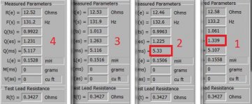
Ok, after 2 days of playing static at a fairly quiet volume, the final values are in. The question is that two of the drivers have slightly different values (see red boxes in the last two (#2 & #1)), but I'm not sure if I'm being anal, or if there is something here to worry about (order a spare driver or two and return these, or...)
Is there a 'right way' to group these in pairs for the Karlsonator foamcore boxes?
Attachments
")
+1 they look good and since design is quite forgiving, don’t worry about it. Matching Vas and Qts so that left and right channels have same average values are probably the ones to look for if you insist on some reason to do so. Start building!
Thanks perceval & xrk971, just wanted to make sure things were not too wonky. I'm not particularly familiar with this territory, so I though I'd seek a guide. Moving onward, in my copious spare time...
Here is a possible budget solution to a full size Karlsonator 12 fitted with four PA130-8 in series parallel for 97dB sensitivity. The drivers are MCM but looks and specs appear very close to PA130-8. I just got 8 for $56 shipping included.
http://www.diyaudio.com/forums/full...onator-0-53x-dual-tc9fds-274.html#post5405805
http://www.diyaudio.com/forums/full...onator-0-53x-dual-tc9fds-274.html#post5405805
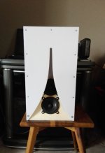
I've uploaded the plans of the 53% scale Karlsonators with dual FaitalPro 3FE25-16's in this post.
It's for 5mm foam core board - not the plans I posted earlier in this thread for 12mm MDF.
.
It's for 5mm foam core board - not the plans I posted earlier in this thread for 12mm MDF.
.
Attachments
I had heard that the ACAs weren’t at their best into 4 ohms. But clearly they will work well based on some reports here. Theoretically ACA Parallel monoblocks should handle 4ohms better. (!)
Mark Fenlon got tired of maintaining his Markaudio forum here or got tired of us, or something, so it’s not operational.
Fostex 103’s sound quite good with ACAs IMHO. If not played too loud. Great for a desktop. On less complex music work wellin rooms it not pushed
Mark Fenlon got tired of maintaining his Markaudio forum here or got tired of us, or something, so it’s not operational.
Fostex 103’s sound quite good with ACAs IMHO. If not played too loud. Great for a desktop. On less complex music work wellin rooms it not pushed
Last edited:
Fostex FFWK series, 165 or 205 - the latter need tweeters for some ears- and any of the Mark Audio 10cm class would be on my short list of nominees.
I’ve personally found the Fostex FExx6 series and the TB 1772s a bit too coloured - each in their own way.
Of course, the space available - and degree of complexity you’re comfortable with certainly come into play.
I’ve personally found the Fostex FExx6 series and the TB 1772s a bit too coloured - each in their own way.
Of course, the space available - and degree of complexity you’re comfortable with certainly come into play.
I had heard that the ACAs weren’t at their best into 4 ohms. But clearly they will work well based on some reports here. Theoretically ACA Parallel monoblocks should handle 4ohms better. (!)
Parallel will halve the output impedance and give better match wit 4Ω loads, bridged 2x the output impedance and each channel will see half the load, so not so good into low impedances.
dave
Can you guys recommend any commercially available, high efficiency, speakers for ACA? Possibly 2-way for under $500/pair? The only ones I'm aware of that might be good, (not 2-way) are Maggies. Are there any famously good speakers in that range that a person can just go buy (Elac?) that you guys know work well with ACA?
- Status
- This old topic is closed. If you want to reopen this topic, contact a moderator using the "Report Post" button.
- Home
- Loudspeakers
- Full Range
- ACA Speaker short list