I've been EQing my transmission line speakers using a miniDSP. This is nice, as it gives me a lot of flexibility to correct the shape of the response. However I'd like to take the DSP away at some point and use an analog active EQ, because it's quite a lot cheaper and simpler, and because analog circuitry plays nice on the quiet side of the volume control.
However I haven't had a lot of joy getting an EQ with the fast second-order slope that my speakers want. The published designs tend to have slow rolloff, and the Linkwitz transform, combining a shelf and a notch, just clobbers the bottom octave of the speaker.
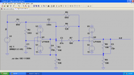
Anyway, I thought I'd experiment a bit, and think I might have a workable solution. I started with a simple Sallen-Key low-pass, with a voltage divider in the negative feedback loop to allow for higher Q (and hence faster roll-off). Then I simply used a second stage to sum the output from my low-pass with the original signal.
It wasn't ideal, as the phase shift from the low-pass still created a reasonably deep notch an octave above the cutoff frequency. I cleaned this up by adding an RC element to sum an additional further phase shifted version of the filtered component. That gives us an extra pole that we can tune to correct for the notch.
The result is as shown. R1, R2, C1, C2 set the cutoff frequency. R3, R4 sets the Q. The shelf depth is set by R5 and R6, and the depth of the notch can be tuned by C3 and R7.
The values shown give a 10dB shelf with a small 14dB peak at ~65Hz, and no gain from about 100Hz on. This should correct the response from my SB12NRX transmission lines nicely.
However I haven't had a lot of joy getting an EQ with the fast second-order slope that my speakers want. The published designs tend to have slow rolloff, and the Linkwitz transform, combining a shelf and a notch, just clobbers the bottom octave of the speaker.
Anyway, I thought I'd experiment a bit, and think I might have a workable solution. I started with a simple Sallen-Key low-pass, with a voltage divider in the negative feedback loop to allow for higher Q (and hence faster roll-off). Then I simply used a second stage to sum the output from my low-pass with the original signal.
It wasn't ideal, as the phase shift from the low-pass still created a reasonably deep notch an octave above the cutoff frequency. I cleaned this up by adding an RC element to sum an additional further phase shifted version of the filtered component. That gives us an extra pole that we can tune to correct for the notch.
The result is as shown. R1, R2, C1, C2 set the cutoff frequency. R3, R4 sets the Q. The shelf depth is set by R5 and R6, and the depth of the notch can be tuned by C3 and R7.
The values shown give a 10dB shelf with a small 14dB peak at ~65Hz, and no gain from about 100Hz on. This should correct the response from my SB12NRX transmission lines nicely.
Attachments
I don't follow the logic or lack of, in your post.
What Fc and Q are the stages in your DSP implementation of a second order filter? What alignment, bessel, bw?
I cannot see a good reason to arbitrarily increase Q Without following your design....seems like a waste of time to me. Besides....Sallen key is only stable for Q less than 3, so watch you haven't passed that point.
I've built up to a 5th order Chebyshev ish filters in Sallen Key with no issues.
List your stage Qs and Fc.'s and alignment and I'll have a look on the simbobulator
The DSP software simply asks for frequency, Q and attenuation when creating a shelf. I presume it's implementing a second order filter but have no idea what it actually does under the hood.
Increasing Q allows me to create a peak at Fc and a sharper rolloff. This is kindergarten stuff. I simply match the size of the peak to the dip in my response curve to correct it. In this case gain is 2.5, so Q is 2. I thought that was obvious.
Increasing Q allows me to create a peak at Fc and a sharper rolloff. This is kindergarten stuff. I simply match the size of the peak to the dip in my response curve to correct it. In this case gain is 2.5, so Q is 2. I thought that was obvious.
Right up front, I love analogue design. Refer to the end - +14dB is actually a fair bit at low frequencies...
That said, in driving speakers I have gravitated to a digital solution as the rigidity of an analogue solution is frustrating, and in the end of the day a good digital implementation is as quiet as analogue.
The choice of analogue vs DSP is one that in my experience is not as obvious as you might think.
- Noise (and distortion) at low levels using DSP is in my experience a result of the quality of ADC and DAC.
I have played with a number of ADC and DACs and once you use good quality buffers and filters noise is not a problem. nor is distortion from the measurement s I have done. The CS3310 I used introduced more distortion than the CS4398 driving it.
- Cost
Is a real issue. I have not bought the minidsp gear - though I do use the AD DSP ICs. The actual cost of the DSP hardware is probably an order of magnitude more than analogue, and the complexity two orders of magnitude if you count the software.
- Adaptability
Your experience with the analogue implementation of the filter is a good case in point - getting odd responses from pure analogue circuitry gets very fiddly indeed.
Comment:
- I think you might want to look at the cone excursion on that woofer! +14dB at / around its cutoff could be leading to some challenging asks of that little driver!
- There are less obvious issues that you might consider like distortion, and the fact you will be asking that SB woofer to generate higher frequencies - you will get phase modulation on the higher frequencies caused by the large excursions the woofer is making.
The DSP software simply asks for frequency, Q and attenuation when creating a shelf. I presume it's implementing a second order filter but have no idea what it actually does under the hood.
Increasing Q allows me to create a peak at Fc and a sharper rolloff. This is kindergarten stuff. I simply match the size of the peak to the dip in my response curve to correct it. In this case gain is 2.5, so Q is 2. I thought that was obvious.
Oh the irony.
First off....your filter transfer function wants to be the inverse of the speaker's.
I am assuming you're trying to linkwitz it.
So depending on exact TL damping and alignment you want a 2nd, 3rd or 4th order slope.
Increasing Q to 2 may help you get there but isn't the way to achieve that slope. Try another stage. And set Fc and Q based on textbook butterworth alignment.
Then you can tweak the Fc to slope match.
That is kindergarten stuff. Do that right first. This is a prefect example of bad use of DSP and misunderstanding of the task at hand.
Implement a infrastructure HP filter to stop your woofers bouncing their coils out the gap permanently.
A good DSP matches analogue design....while your volume is maxed out and you're not throwing bits away....
Peace.
Last edited:
I agree broadly with what you say. My miniDSP is a wonderful bit of kit that makes this job incredibly easy. Also agree that 14dB is a fair bit of gain down low and really I think as far as you can push these little things. The SB12NRX has a reasonably high Xmax (5mm), and including EG (with DSP) I'm getting ~1% THD at 50Hz for a pair. My hope is that by adding more drivers I can push that down somewhat.
Hi Suzyj,
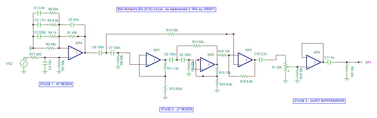
I like miniDSP too and when possible I like to do stuff in analog, like passive crossovers and such. I also like op amp based filters if they are simple and quiet. 14dB is not too much boost if you are going to make a line array of the TC9's. A few years, I worked with Bob Richards on an all op-amp analog EQ circuit for the IDS-25 line array (uses 25 x TC9FD's).To get sufficient boost for bass, the gain was huge (circa 9dB at 50Hz) but not an issue if you have lots of drivers as the 25 TC9's has same Sd as a 15in driver. What I found that was useful is that since I model all my speakers in Akabak, I could actually implement the op amp filters as an Akabak network. This then lets me tie it ito the driver TS params and the speaker cabinet sim all in one. Then you could predict cone excursion, freq response, comb filtering effects, etc. Unfortunately, Akabak has limit of 55 nodes so I ran out of nodes with the speaker having 25 drivers and all the op amp circuit parts.
Cloning IDS-25s
Here was Bob Richards's circuit:
Here is my sim of Bob's circuit in TINA (before I switched to LTSpice):
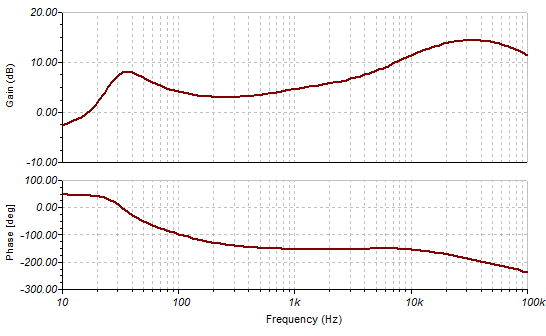
Resulting gain function:
The next task was to take a sim of a 25 driver array in Akabak and try to implement the op amp EQ inside Akabak...:
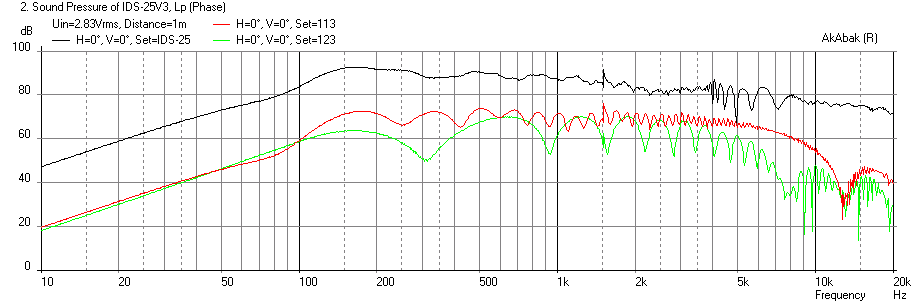
This was as far as I got on the circuit in Akabak:
But nowadays, we do all this in miniDSP or in Jriver as a convolution or PEQ banks and save our opamps for another use.")
I like miniDSP too and when possible I like to do stuff in analog, like passive crossovers and such. I also like op amp based filters if they are simple and quiet. 14dB is not too much boost if you are going to make a line array of the TC9's. A few years, I worked with Bob Richards on an all op-amp analog EQ circuit for the IDS-25 line array (uses 25 x TC9FD's).To get sufficient boost for bass, the gain was huge (circa 9dB at 50Hz) but not an issue if you have lots of drivers as the 25 TC9's has same Sd as a 15in driver. What I found that was useful is that since I model all my speakers in Akabak, I could actually implement the op amp filters as an Akabak network. This then lets me tie it ito the driver TS params and the speaker cabinet sim all in one. Then you could predict cone excursion, freq response, comb filtering effects, etc. Unfortunately, Akabak has limit of 55 nodes so I ran out of nodes with the speaker having 25 drivers and all the op amp circuit parts.
Cloning IDS-25s
Here was Bob Richards's circuit:
Here is my sim of Bob's circuit in TINA (before I switched to LTSpice):
Resulting gain function:
The next task was to take a sim of a 25 driver array in Akabak and try to implement the op amp EQ inside Akabak...:
This was as far as I got on the circuit in Akabak:
Code:
|********************************************************
| Sim of Bob Richards IDS-25 EQ Circuit in Akabak
| XRK971, Sept 5, 2013
|
| Simulation: Inspect/Voltage (Level)

| Define operational amplifier
  Def_OpAmp  'Op1'
  vo=1e6  Rg=10ohm

System 'EQ High'

| #### SECTION 1 - High End Response EQ

  OpAmp  'Op1'  Def='Op1'  Node=2=3=4
  Capacitor  'C1'  Node=2=0  C=10nF
  Resistor  'R1'  Node=1=2  R=200ohm
  Resistor  'R2'  Node=2=0  R=50kohm
  Capacitor  'C2'  Node=5=0  C=3.9nF
  Resistor  'R3'  Node=3=5  R=50kohm
  Capacitor  'C3'  Node=6=0  C=1.5nF
  Resistor  'R4'  Node=3=6  R=6.8kohm
  Capacitor  'C4'  Node=7=0  C=330pF
  Resistor  'R5'  Node=3=7  R=1kohm
  Capacitor  'C5'  Node=3=4  C=82pF
  Resistor  'R7'  Node=3=4  R=40kohm
  Potential    'Out H-EQ'  Node=4=0

| #### SECTION 2 - Low End Response EQ


|System 'EQ Low'

  OpAmp  'Op2'  Def='Op1'  Node=9=10=11
  Capacitor  'C6'  Node=4=8  C=100nF  | (Node=4=8)
  Capacitor  'C7'  Node=8=9  C=100nF
  Resistor  'R8'  Node=9=0  R=50kohm
  Resistor  'R9'  Node=11=10  R=12kohm
  Resistor  'R10'  Node=10=0  R=9.6kohm
  Capacitor  'C8'  Node=11=12  C=100nF
  Capacitor  'C9'  Node=12=13  C=100nF
  Resistor  'R11'  Node=13=0  R=50kohm

  OpAmp  'Op3'  Def='Op1'  Node=13=14=15
  Resistor  'R12'  Node=15=14  R=12kohm
  Resistor  'R13'  Node=14=0  R=9.6kohm
  Resistor  'R16'  Node=12=15  R=50kohm
  Resistor  'R17'  Node=8=17  R=50kohm

  OpAmp  'Op4'  Def='Op1'  Node=17=18=19
  Resistor  'R14'  Node=15=18  R=12kohm
  Resistor  'R15'  Node=18=19  R=6.8kohm
  Capacitor  'C10'  Node=19=20  C=2.2uF
  Potential    'Out L-EQ'  Node=20=0

| #### SECTION 3 - Level Control Buffer and Line Driver


|System 'EQ Buffer'

  Resistor  'P1U'  Node=20=21  R=1kohm  | (node 20=21) Adjustment Pot upper
  Resistor  'P1L'  Node=21=0  R=19kohm   | Adjustment Pot lower set at 1:19 position

  OpAmp  'Op5'  Def='Op1'  Node=21=22=22
  Resistor  'R18'  Node=21=0  R=1Mohm
  Resistor  'R19'  Node=22=23  R=200ohm
  Capacitor  'C11'  Node=23=24  C=5uF
  Resistor  'R20'  Node=24=0  R=100kohm
  Potential    'Out Buffer'  Node=24=0  | Inspect this node for total ouput
But nowadays, we do all this in miniDSP or in Jriver as a convolution or PEQ banks and save our opamps for another use.
Last edited:
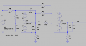
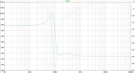
Here's a quick test of the real thing with my speaker.
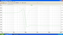
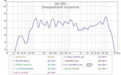
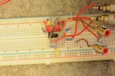
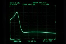
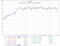
I've attached the schematic I ended up with to EQ this speaker - rather less bass boost was needed, plus a photo of the nasty prototype and the actual measurements, both of the prototype transfer function using my spec-an and tracking generator and finally a comparison of the correction I'm able to achieve with DSP vs that with the opamp circuit.
It gives me a reasonably accurate correction of the TL rolloff. There's a bit of a dip at 150Hz that's of rather higher Q than I can easily correct for, and you can see that my attempt to deal with it has left me with a bit of a peak at 120Hz, but on the whole I'm pretty happy with the circuit. It's amazing how many ergs you can squeeze from a poxy 4" driver.
Attachments
Last edited:
- Status
- This old topic is closed. If you want to reopen this topic, contact a moderator using the "Report Post" button.
- Home
- Loudspeakers
- Full Range
- A high-Q opamp shelf filter for EQing transmission lines and the like