I'm working on two 6 liter ported full range speaker using Tang Band W3-871B drivers, but I'm running into a lot of resonance issues around 380hz (going on in the vertical axis, most likely). Knocking them up with either foam around the edges or stuffing stuffing in there does not seem to help a great deal. What could I do to reduce what's going on in there?
Thanks a lot!
An externally hosted image should be here but it was not working when we last tested it.
An externally hosted image should be here but it was not working when we last tested it.
Thanks a lot!
At least a couple of things I can think of happening, likely .
Due to the ratio of narrow cross sectional area and length, you'll be getting some internal resonances at frequencies related to the dimensions. Enclosures of this shape are often modeled to operate vented, and careful placement of the driver further down the long axis can mitigate the peaks and dips seen in your measures.
Foam isn't a particularly effective damping material at lower frequencies, and you've likely got some panel resonances as well. Try a couple of bracing ribs or dowels connecting each of the opposing long panels - not spaced at the middle of each, and not at the same distances from front to back and side to side.
The real smart guys here should soon pipe in with more thorough explanations .
Looks to me like a standing wave, likely top-to-bottom. I have some speakers here with the same problem.
If you make the top and bottom non-parallel, that'll likely help. Even just putting a couple of tins of beans in the bottom laid down (so the curved surface is facing the top of the enclosure) will likely break things up a bit.
Chris
If you make the top and bottom non-parallel, that'll likely help. Even just putting a couple of tins of beans in the bottom laid down (so the curved surface is facing the top of the enclosure) will likely break things up a bit.
Chris
380Hz has a wavelength of just under 36", so at multiples and 1/2 , 1/4 etc fractions thereof, those internal nodes will likely occur.
Chris's suggestion is certainly as good as any - although I'd be inclined to something like pieces of ABS plumbing pipe filled with dry sand.
What are the 3 internal dimensions?
As an afterthought, a couple of horizontal shelf braces with a number of large holes at uneven locations might help to break-up / randomize those reflections, and lining the walls with thicker fiberglass as opposed to the corrugated foam probably couldn't hurt.
Last edited:
Wow, thanks for all the detailed responses! Great people on here.
Next up I cut the blocks into halves and press fit them in like this:
This set the frequency back to 300hz, but made a huge dip up to 500hz:
Blocking the port (I should have told you it was ported at the start) brings the dip back up, but still has the resonance:
I'm measuring about 40cm from the speaker, halfway between the port and the driver.
Is fiberglass the trick from here on? Also, could anyone explain what's going on between 300 and 500hz when I keep the port open?
Thanks again for the help so far!
These are 126 x 109 x 464mm. I put them into the internal standing wave calculator from Vikash Chauhan, the vertical standing wave mood does indeed seem to be responsible for the problem.What are the 3 internal dimensions?
I tried this, but it somehow made it worse? I put two 18mm panels at a +-10 degree angle at the top and botton, here's the measurement:If you make the top and bottom non-parallel, that'll likely help.
An externally hosted image should be here but it was not working when we last tested it.
Next up I cut the blocks into halves and press fit them in like this:
An externally hosted image should be here but it was not working when we last tested it.
This set the frequency back to 300hz, but made a huge dip up to 500hz:
An externally hosted image should be here but it was not working when we last tested it.
Blocking the port (I should have told you it was ported at the start) brings the dip back up, but still has the resonance:
An externally hosted image should be here but it was not working when we last tested it.
I'm measuring about 40cm from the speaker, halfway between the port and the driver.
Is fiberglass the trick from here on? Also, could anyone explain what's going on between 300 and 500hz when I keep the port open?
Thanks again for the help so far!
As for braces, I was thinking more along the lines of a holey brace as is often seen in drawings by DaveD - but I'd missed in your first post that these were ported - that actually changes things quite a bit.
What I think you've now got is a sub-optimally tuned quarter wave resonator / MLTL of sorts, and I don't think all the fibreglass you could fit in the box would remedy the situation before it provides too much mass load on the driver.
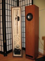
The location of the driver along that line can significantly affect the distribution of resonances, and any braces should be oriented to provide as narrow a cross section in the longitudinal direction as possible - i.e. vertically.
I'll repost a photo that sorta shows what I'm getting at - this is of course before internal stuffing - Acoustistuff, not foam - is installed
What I think you've now got is a sub-optimally tuned quarter wave resonator / MLTL of sorts, and I don't think all the fibreglass you could fit in the box would remedy the situation before it provides too much mass load on the driver.
The location of the driver along that line can significantly affect the distribution of resonances, and any braces should be oriented to provide as narrow a cross section in the longitudinal direction as possible - i.e. vertically.
I'll repost a photo that sorta shows what I'm getting at - this is of course before internal stuffing - Acoustistuff, not foam - is installed
Attachments
The deflectors have spread out the resonances. Applying some absorption on the surface of those might just do enough to sort things out. IIRC foam is good for high-frequency absorption, but won't do much below 1kHz. Densely packed polyester filling (pillows, cushions, etc) usually does better.
By making the top and bottom non-parallel, I was thinking a board at the top or bottom of the cabinet that's at 45 degrees (maybe steeper, 60 degrees?). Something to break up the single, strong resonance. Make sure the panels you put in are not parallel, or you're back to square one.
Since blocking the port helps, is there any chance you can put the port on the back of the enclosure? That puts an acoustic filter between the port and the room, might help a little.
Chris
Stuff whole top third (or half) of the volume with mineral wool (Rock Wool) - whole third volume, not just linings on the walls. It will kill the resonance.I'm working on two 6 liter ported full range speaker using Tang Band W3-871B drivers, but I'm running into a lot of resonance issues around 380hz (going on in the vertical axis, most likely).
how is the baffle being held in place to get a measurement?
i don't see any screw holes in either the baffle or the box. adding bar clamps will mass load the box.
and ratchet straps don't guarantee the mating parts are sealed?
could just be the front baffle being a kazoo at 350 hz
i don't see any screw holes in either the baffle or the box. adding bar clamps will mass load the box.
and ratchet straps don't guarantee the mating parts are sealed?
could just be the front baffle being a kazoo at 350 hz
turk - indeed, that was too bloody obvious. This is a good time to get a sounding on something that's always intrigued me: many times we'll see photos of temporary set-ups with a varying number of clamps holding on that "last side" during testing /measurements.
Even if that does give an air-tight seal, I can't imagine that the extra mass of all those clamps, plus the likely greater tensions on the panels than present when completed wouldn't affect the enclosure's resonant characteristics. Opinions or even documented tests on that supposition?
In such cases, I'll use a gasket of foam weatherstrip tape and screws - as I always tart up any successful build withe veneer, etc., those holes will get filled and covered over. The heroic failures will be sacrificed to the great carbon recycling in the sky - we still are permitted bonfires in the lower risk seasons.
 (mdf is nasty creosote for a chimney flue)
Thank you for all the great responses!
I think it's definitely a driver placement issue. I've creatively rearranged the panels to move the driver and port down a bit, which completely eliminates the resonance without any stuffing or damping in there.
I'll play with the arrangement some more and keep you up to date!
I think it's definitely a driver placement issue. I've creatively rearranged the panels to move the driver and port down a bit, which completely eliminates the resonance without any stuffing or damping in there.
An externally hosted image should be here but it was not working when we last tested it.
An externally hosted image should be here but it was not working when we last tested it.
I'll play with the arrangement some more and keep you up to date!
how is the joint between the two panels sealed?
not to mention that now your baffle is made up of two pieces not one, how does one reconcile that condition in the final build?
cheap analogy: if you split a drum skin does it sound the same.
not saying that driver placement is not a factor any distance that keeps you away from 1/4,1/2 wavelength ratios helps.
interesting to note that now the port is at the mid point of the enclosure and the driver is at about a third, but distance driver to port has decreased.
when ever I have played with this, port lengths end up being more "as calculated" in this type of arrangement, than if they are located at the opposite end from the driver. It knocks out any 1/4 wave action from the enclosure that might otherwise contribute to the LF.
Worth considering however, that a lot more mid-HF is likely to find its way out of that port with it much closer to the driver.
- Status
- This old topic is closed. If you want to reopen this topic, contact a moderator using the "Report Post" button.
- Home
- Loudspeakers
- Full Range
- Resolving resonance in tall full range tower?