Generally, even-sided objects have inversion symmetry. Meaning you could put a mirror along the inversion symmetry plane and be able to reproduce the object. So squares, rectangles, hexagons, (and even circles technically) have inversion symmetry. Odd-sided objects like triangles and pentagons cannot be mirrored. So this means that there is not a flat-to-flat parallel wall for a resonance to set itself up. Circular or rotational symmetry is better than flat-flat but a circle in itself has resonance mode (breathing mode - radial direction and tangential parallel to round wall in a loop or so called whispering gallery mode). For odd numbered walls you don't want to go to high as then it approximates a smooth circle. This concept also applies to drumheads or membranes. The Vifa TC9FD and cousins (TG9, 10F, etc) have a patented pentagonal membrane (you can see it on underside of cone and where it is glued to surround). This is one way to get rid of traditional drum-head vibration modes on cone. Hence it is very smooth and relatively breakup free.
Delay Mid/ High
Dear XRK971,
in thread 876 you wrote, that with that crossover and a 30in tall stand and the woofer on top, the delay of the mid/ high driver is just right for transient perfect. - On what height are your ears at that moment? What point between mid/ high and woofer is at which angle optimal for that setting/ crossover?
I prefer a tweeter on top, I guess I may use it my way, as long as I stay with the right angle and height, right?
Thank you very much for sharing this speaker with us,
Florian
Dear XRK971,
I prefer a tweeter on top, I guess I may use it my way, as long as I stay with the right angle and height, right?
Florian
Just tilt your speakers back a little to achieve time alignment with the FR drivers on top.
Dear XRK971,
in thread 876 you wrote, that with that crossover and a 30in tall stand and the woofer on top, the delay of the mid/ high driver is just right for transient perfect. - On what height are your ears at that moment? What point between mid/ high and woofer is at which angle optimal for that setting/ crossover?
I prefer a tweeter on top, I guess I may use it my way, as long as I stay with the right angle and height, right?
Thank you very much for sharing this speaker with us,
Florian
The setback needed is about 3in, and it seems if speakers are set with ears at woofer level axis, the timing is correct for listening position 1.5m or greater. The farther away, the less stringent the requirement and you could flip it the other way. However, if you look at the vertical polar plots, the sweet spot is wider with this setup.
Dear XRK, thank you for your answer. Please excuse for asking again, I'd like to take it seriously. You said 3in, is this the difference of the distances measured from the acoustical centers/ the voice coils, or is it from the most front point of each driver, let's say the basket/ mounting of the drivers/ front baffle?
When the ear is on the axis of the woofer, according to my understanding there is only one distance to the whole speaker, where the offset of the two drivers is exactly the 3in. Is this the 1,5m? The further away one gets, the less the offset of the two drivers becomes. In opposite, just right in front of the woofer, the distance offset to the mid/ high driver is maximal, it is the 7,5in distance between the two drivers on the front baffle.
I know that most people tend to position their speakers rather low on small stands, but in my case they would be rather high, so just turning them upside down, the mid/ highs on top, could actually work well for me.
For the 10F and RS232, the setback happens to be 3in as measured from the bezel front. Technically you are right that only 1 distance perfectly satisfies the time alignment. But in practice it works over a wide range if you look at measured step response and also in listening. My speakers are on rather high 3ft talk stands and it works well for standing listening position.
I am fussy...or hopefully just trying to be correct: I have just calculated, that 3in offset, and the ear on the woofer axis, actually means a listening distance of 7,875in, 20cm... But I guess, I wouldn't make the speaker even more correct, setting the 10F 3in back listening on the axis right between the drivers... right? Sorry... I am not a very experienced speaker designer, I guess I just try to understand that what you wrote, and when you say 3in offset, this acutally comes to my mind.
crossover 4,4uF and 0.47R?
Dear XRK,
do you stay with these additional components C3 and R5, 4,4uF and 0.47R for the woofer, as shown in thread 945? Perhaps I jumped it when reading, but I actually didn't find it - what's the reason for this update, what good does it cause?
Thank you, Florian
Dear XRK,
do you stay with these additional components C3 and R5, 4,4uF and 0.47R for the woofer, as shown in thread 945? Perhaps I jumped it when reading, but I actually didn't find it - what's the reason for this update, what good does it cause?
Thank you, Florian
Dear XRK,
do you stay with these additional components C3 and R5, 4,4uF and 0.47R for the woofer, as shown in thread 945? Perhaps I jumped it when reading, but I actually didn't find it - what's the reason for this update, what good does it cause?
Thank you, Florian
Yes, please use the added 4.4uF and 0.47R. It helps to reduce the RS225’s cone breakup modes from leaking through. Actually a substantial 20dB reduction and helps it sound overall a lot more clear.
okay, great. Sounds very promising. I am very excited. Thank you!
Good luck on the build and don’t hesitate to ask questions if you get stuck.
Regards,
X
Thank you. I am still planning... can't afford the material yet. I have installed a loudspeaker crossover simulation program, I simulated a bigger 4mH inductor with only 0,72 Ohm, instead of 1,21 Ohm internal resistance, it seems to produce 0,5dB more bass... I read very promising reviews on partsexpress with this thicker coil. I think I am gonna put a 10W 0,47Ohm resistance with this inductor in series, to get the calculation you did, and hear the difference, if there is any difference in transients for example.
Thank you,
Florian
Thank you,
Florian
Adding R increases the Q and deepens bass at expense of sensitivity. Reducing R increases sensitivity but reduces bass extension. Probably try it without the 0.47R and decrease the 10R padding resistor on the midtweeter to level balanced. You don’t want to pad the woofer under any circumstance.
Last edited:
Hello X,
Summer treating you better or still crazy busy?
I said I wanted to try this, but using my Brio clone instead.
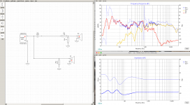
Basically, it's a W8-1363SBF in a vented enclosure, the middle B80 with downslope "ceiling" to look like a dagger above that, and then a B80 in OB on top... so variations on your theme.
Variations didn't stop there, as I let the SBF run free. It has an ok down slope after 1kHz.
The dual B80s are on a single 25uF cap, and a small L-Pad. A 8 Ohms resistor to bring global impedance down. That's it. Super simple.
My XO is much higher than your 500Hz point, though. I'll look into adding a bigger cap to see if I can let the B80s play a little more of the spectrum. 25uF is the biggest I have at home right now.
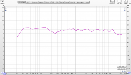
Didn't have much time to take measurements, but it does look very promising! The 200Hz dip is room related, and I would only need to move the speakers around to get rid of that.
The drop at 13kHz is probably due to the B80s spacing and position... I'll need to play with that.
But I'm pretty stoke with this first shot!
XO measurements taken at 1m. FR sweep taken at listening position, about 3m away.
Summer treating you better or still crazy busy?
I said I wanted to try this, but using my Brio clone instead.
Basically, it's a W8-1363SBF in a vented enclosure, the middle B80 with downslope "ceiling" to look like a dagger above that, and then a B80 in OB on top... so variations on your theme.
Variations didn't stop there, as I let the SBF run free. It has an ok down slope after 1kHz.
The dual B80s are on a single 25uF cap, and a small L-Pad. A 8 Ohms resistor to bring global impedance down. That's it. Super simple.
My XO is much higher than your 500Hz point, though. I'll look into adding a bigger cap to see if I can let the B80s play a little more of the spectrum. 25uF is the biggest I have at home right now.
Didn't have much time to take measurements, but it does look very promising! The 200Hz dip is room related, and I would only need to move the speakers around to get rid of that.
The drop at 13kHz is probably due to the B80s spacing and position... I'll need to play with that.
But I'm pretty stoke with this first shot!
XO measurements taken at 1m. FR sweep taken at listening position, about 3m away.
Attachments
Looks pretty good actually for running full range on the woofer. A 4mH inductor may help to lower that to maybe 800Hz, and a 50 to 60uF cap will lower the XO point. Just use two 100uF electrolytic caps back to back (+/-/-/+) bypass with 2.2uF film cap and it is a cheap and good sounding way to achieve larger values. For inductor, you can use iron plate or ferrite core ones to reduce cost vs aircores.
- Home
- Loudspeakers
- Full Range
- 10F/8424 & RS225-8 FAST / WAW Ref Monitor