") running Win7 64, so a virtual machine should do the job. Will try it out when I get chance.
running Win7 64, so a virtual machine should do the job. Will try it out when I get chance.Yes, it's looking very much like the driver's height and speaker placement is going to dictate the XO and how far below 1KHz it could be done. The baffle size should really allow ~300-400Hz XO with broad, gentle EQ above 500Hz on the peaks... in reality it's looking more like 700Hz or higher.
This is why I'm loving miniDSP units, as they allow easy tweaking once the speakers are in place
Not quite ready to start making anything, maybe another couple of weeks... One more set of measures to do with the test baffle, then sorting the data out to be presented. Plus about 30 minutes work to do on the miniSharc enclosure so that's completed.
A narrow OB is defiantly on the cards, whether this is to be a 4" wide range [FR] driver and 15" woofer or something a bit more elaborate is yet to be decided
A narrow OB is defiantly on the cards, whether this is to be a 4" wide range [FR] driver and 15" woofer or something a bit more elaborate is yet to be decided
Almost Done
Final set of measurements have been done this morning, shouldn't take to long to sort through the data and put it into some kind of order...
Full set include; full baffle, 2", 2.5", 3", 3.5", 4", 4.5", 5", 5.5" and 6" cut out around a 14cm x 21cm inner baffle, with a Vifa TC9FD driver centred 15.5cm from the top edge. Didn't listen to any music as I progressed, so o listening impressions, sorry.
Paul
Attachments
BMS,
Wow! Nice effort here to get all this data. One of the most extensive polar response studies on a dipole and baffle cutout I have seen. Looking forward to seeing the results. Are you enlarging the cutout as you go? That is, you don't have separate baffles that you can go back to do you?
Wow! Nice effort here to get all this data. One of the most extensive polar response studies on a dipole and baffle cutout I have seen. Looking forward to seeing the results. Are you enlarging the cutout as you go? That is, you don't have separate baffles that you can go back to do you?
Data! Data!
First off, I'd like to say that I have actually enjoyed doing this little bit of research. It's not been done in the most scientific of ways or in a perfect environment. I've tried to be consistent and minimise any room related issues as far as possible... It was done in my living room after all.
Question... while retaining the look of a wider Open Baffle, how wide [or narrow] a cut-out around the driver is needed to aid polar response, thus giving a more even Omni-directional sound... That's what I think it was about anyway
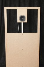
The Test... take an Open Baffle fitted with a Vifa TC9FD driver, cut a U-shaped slot around the driver, measure the response from 0° to 90°. Make the cut wider then re-measure, and repeat. Microphone set at driver height [87.5cm] and 1meter distance
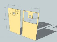
The Baffle... 20" x 38" [505mm x 965mm]. Vifa unit is mounted centrally 155mm from the top edge. The initial 2 inch U-cut is made around a 140mm x 210mm inner baffle size. Each successive cut increased the width/depth by 0.5 inches. The final cut-out is 6 inches, leaving a 1 inch outer frame formed by the original baffle.
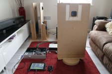
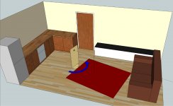
The Environment... My living room, wooden floor with a big rug, bits of furniture etc. Tried to move things around to minimise their effect.
The Data... The measurements show the effects of floor reflection, plus 70°, 80° and 90° have a slightly earlier reflection. On some of the polar plots I've adjusted the gating with the data incorporated into the mirrored 0° to -90° plots.
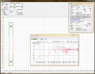
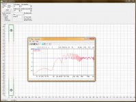
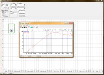
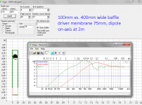
Pictures... 1, Simulated frequency response for the 140mm x 210mm baffle. 2, Simulated response with floor reflection. 3, rough room layout during testing. 4, baffle sizing before and after.
Paul.
First off, I'd like to say that I have actually enjoyed doing this little bit of research. It's not been done in the most scientific of ways or in a perfect environment. I've tried to be consistent and minimise any room related issues as far as possible... It was done in my living room after all.
Question... while retaining the look of a wider Open Baffle, how wide [or narrow] a cut-out around the driver is needed to aid polar response, thus giving a more even Omni-directional sound... That's what I think it was about anyway
The Test... take an Open Baffle fitted with a Vifa TC9FD driver, cut a U-shaped slot around the driver, measure the response from 0° to 90°. Make the cut wider then re-measure, and repeat. Microphone set at driver height [87.5cm] and 1meter distance
The Baffle... 20" x 38" [505mm x 965mm]. Vifa unit is mounted centrally 155mm from the top edge. The initial 2 inch U-cut is made around a 140mm x 210mm inner baffle size. Each successive cut increased the width/depth by 0.5 inches. The final cut-out is 6 inches, leaving a 1 inch outer frame formed by the original baffle.
The Environment... My living room, wooden floor with a big rug, bits of furniture etc. Tried to move things around to minimise their effect.
The Data... The measurements show the effects of floor reflection, plus 70°, 80° and 90° have a slightly earlier reflection. On some of the polar plots I've adjusted the gating with the data incorporated into the mirrored 0° to -90° plots.
Pictures... 1, Simulated frequency response for the 140mm x 210mm baffle. 2, Simulated response with floor reflection. 3, rough room layout during testing. 4, baffle sizing before and after.
Paul.
Attachments
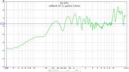
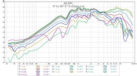
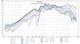
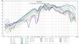
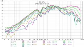
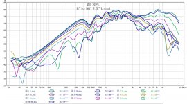
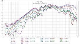
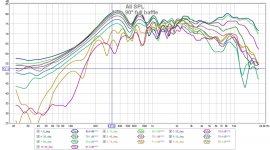
Ten sets of data measuring the baffle with no cut out, then increasing width of U-shaped cut out from 2 inches to 6 inches in 1/2 inch steps...
First sets are the full 0° to 90° frequency response for 0", 2", 2.5", 3", 3.5", 4", 4.5", 5", 5.5" and 6".
Data uses 5ms right gating and 1/6 smoothing.
First sets are the full 0° to 90° frequency response for 0", 2", 2.5", 3", 3.5", 4", 4.5", 5", 5.5" and 6".
Data uses 5ms right gating and 1/6 smoothing.
Attachments
-
 0 to 90 6_in cut.jpg230 KB · Views: 112
 -
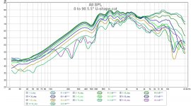 0 to 90 5-5_in cut.jpg222.2 KB · Views: 97
 -
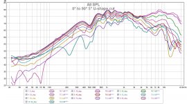 0 to 90 5_in cut.jpg223 KB · Views: 94
 -
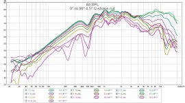 0 to 90 4-5_in cut.jpg229.7 KB · Views: 97
 -
 0 to 90 4_in cut.jpg228.5 KB · Views: 98
 -
 0 to 90 3-5_in cut.jpg230.9 KB · Views: 99
 -
 0 to 90 3_in cut.jpg223.5 KB · Views: 101
 -
 0 to 90 2-5_in cut.jpg235.5 KB · Views: 104
 -
 0 to 90 2_in cut.jpg232.3 KB · Views: 117
 -
 0 to 90 full ob.jpg237.6 KB · Views: 168
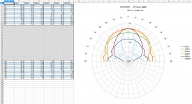
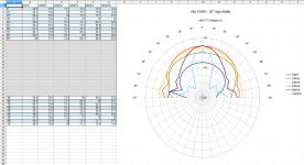
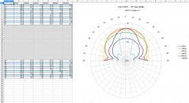
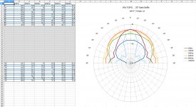
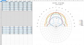
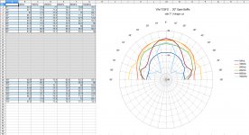
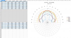
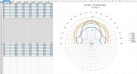
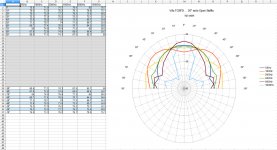
Polar Plots taken at 500Hz, 1000Hz, 2000Hz, 4000Hz, 8000Hz and 16000Hz
Again... earlier gating was used on some of the 70°, 80° and 90° and this is included within the mirrored 0° to -90° portion of the plots.
Again... earlier gating was used on some of the 70°, 80° and 90° and this is included within the mirrored 0° to -90° portion of the plots.
Attachments
-
 PP 0 to 90 4-5_in cut.jpg245.1 KB · Views: 77
 -
 PP 0 to 90 5_in cut.jpg243 KB · Views: 74
 -
 PP 0 to 90 5-5_in cut.jpg242.1 KB · Views: 75
 -
 PP 0 to 90 6_in cut.jpg243.9 KB · Views: 94
 -
 PP 0 to 90 4_in cut.jpg245.7 KB · Views: 76
 -
 PP 0 to 90 3-5_in cut.jpg241.8 KB · Views: 81
 -
 PP 0 to 90 3_in cut.jpg244.5 KB · Views: 80
 -
 PP 0 to 90 2-5_in cut.jpg240.5 KB · Views: 80
 -
 PP 0 to 90 2_in cut.jpg233.1 KB · Views: 98
 -
 PP 0 to 90 full ob.jpg243.6 KB · Views: 106
Yes lots to sift through, being the one doing this has helped massively. Coupled to reading Rudolf's website and SL's ramblings on his LX521 project, I now have an even higher appreciation for those who design speakers
Errr, yes... but like always, there are trade offs. The driver it's self dictates the point at which it starts to beam. The size of the inner baffle dictates the low end roll off and the width of the cut effects the polar response through the midrange.
If we're not going to use tweeters to get the HF figure '8' response, is it worth doing the cutout for the mid range? Think Rudolf [from his site] mentioned Thiele saying people gaining most of the directional information in the 500Hz to 7KHz range.
Again, with the higher low-end roll-off point, we now have to think about a higher XO point. Do we use the same bass units and just push up the XO, or do we add an extra driver to cover this range?
Question, how important is a good figure '8' polar response if it's only one person listening and from a [roughly] fixed point of a listening chair?
BMS; thank you for these very informative and educational measurements!
I find these results to follow dipole/baffle theory and work by Mellow & Kärkkäinen very well! We can see that the best possible dipole peak for this driver/baffle is around 2,5khz. This driver is rather flat and follows model well (model is for flat & pistonic membrane. A narrow opening flattens dipole peak and moves it lower. We also see various diffraction peaks and nulls to move.
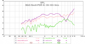
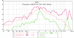
Here is my measurements of Peerless NE95 with no baffle at 0¤ 30¤ and 60¤ Here we notice a problem at 2kHz which is propably caused by the deep and rigid cone. For comparison a nude planar Neo8 in 10cm wide baffle - no peaking until dipole null! 6ms gating 1/12 smoothing, measured at 1m indoors
I find these results to follow dipole/baffle theory and work by Mellow & Kärkkäinen very well! We can see that the best possible dipole peak for this driver/baffle is around 2,5khz. This driver is rather flat and follows model well (model is for flat & pistonic membrane. A narrow opening flattens dipole peak and moves it lower. We also see various diffraction peaks and nulls to move.
Here is my measurements of Peerless NE95 with no baffle at 0¤ 30¤ and 60¤ Here we notice a problem at 2kHz which is propably caused by the deep and rigid cone. For comparison a nude planar Neo8 in 10cm wide baffle - no peaking until dipole null! 6ms gating 1/12 smoothing, measured at 1m indoors
Attachments
I guess I am still not sure why a figure 8 directivity pattern is good. Don't we want uniform over as wide an angle as possible? Or is it a figure 8 pattern most closely resembles natural sources so that directivity and spatial imaging cues can be formed?
What you are asking is what is the advantage of a dipole speaker in the first place. For a dipole to work correctly, the room has to be large enough for the back wave to develop, and the speaker has to be far enough from the wall as to not distort the back wave. The compromises become overwhelming for the DIY'er is a normal sized room. There are easier ways to control directivity, like maybe a constant directivity horn.
I personally believe your work with infinite baffles, which is what your spiral TL really is, is ultimately more productive.
Bob
Dipole 8 radiation for wide range gives many unique sonic/acoustic properties that cannot be achieved in any other way. The problem is that it is practically impossible to construct a loudspeaker that is dipole in full range, even if it is a 4-way construction!
We live and listen to speakers in (acoustically) small rooms and we get lots of reflections and room mode effects to cope with. An open baffle or (partly) dipole speaker usually has uneven power response because of not being true dipole full-range. Work of Olive, Toole, Geddes among others have given us understanding of how loudspekers behave in a room. Power response is composed of a speaker's radiation of soundwaves to all directions in 3D. If we only look at on-axis response and forget the room and power response, we are in trouble! This is the major problem with most OB speakers, which are typically considered to sound dry, harsh, echoye etc. in "wrong" environment. This comes from the fact that most OBs are dipole only below 1000Hz and this leads to loss of "power" below 1000Hz (seen in power response). Nearness to boundaries also makes narrow peaks and dips in response because of early reflections.
Power response quality is difficult to measure. Usually we estimate it based on measurements at 0-90¤ horizontally. Vertical off-axis is also important for multidriver speakers that typically suffer from vertical lobing. Rearwards radiation is important mainly for dipoles. A composistion of all these is power response. The effect of power response can be seen in measurements of decayed room response (decay waterfall) and long-gate and RTA measurements. Listening impression is mostly based on power response.
To sum this up, to see the real performance of a loudspeaker, we must see measurements of:
- on-axis response, phase, distortion, csd up to 3ms
- horizontal and vertical off-axis response (an educated guess can be made based on driver(s) and baffle geometry and crossover types.)
When we set a speaker in a room, we can measure (at/around the listening spot)
- gated room response, L and R separately to see symmetry and room modes
- decay waterfall or spectrogram up to 300ms
- RTA
- EDT, T30, STI
Last edited:
Just one more thing... To be able to measure and evaluate the "things" in my previous post, one must take similar measurements of different types of speakers! I have been learning this for almost a year now (by own measurements) and the first half a year has a steep learning curve!
I have measured some 10 different speakers now - fullrange, multiway, boxed, dipole, waveguides, various test baffles, nude drivers etc. Different distances, indoors, outdoors etc. Now I have developed my own way of understanding causalities - how each construction behaves/measures and how it sounds in my room or outdoors.
I think that I have reached a good level of understanding now. But I learn something new almost every day when I wander around web forums and magazine articles. Who knows what I think and say next year!
Last edited:
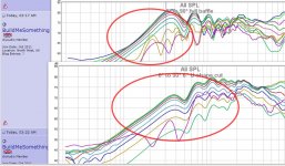
This overlay shows the ranges with controlled directivity (constant and free of diffractions) of TC9 in wide and narrow baffle - circled areas.
We see that lots of eq is needed if we use narrow baffle at low frequencies ( means lots of distortion too) Low end of a dipole is determined by tolerable distortion.
Midrange is very different too - wide baffle has wild variation of response at 300-2kHz because of diffractions. Narrow baffle has smooth response and constant directivity up to 2kHz, where backwave cancellation and diffractions take over.
Above 2,5kHz both have same dispersion, it comes from cone diameter -determined directivity, variations come from cone surround diffractions and cone resonances.
Edge simulation of both too.
Attachments
Last edited:
+1 on post 356. I did some playing with OB's a couple of years back. I used the smallest OB I could that would cross below 300Hz and an H-baffle bass. I used a miniDSP to cross and EQ. I found the room reflections of the back wave from the OB distracting and pretty much destroyed imaging. A single 18" bass driver is not enough to get decent bass even down to 30Hz. I tried this combo in a 12'x15' room and a 15'x25' room and I am not convinced that the H-frame bass has any advantage over a standard sealed sub. I am now using a BR over a sealed sub that is reasonably flat in-room to 20Hz and will to 100dB at 20Hz. I find this much more satisfactory than the OB/H-frame.
As a side note, I am now using the nanoDIGI for XO/EQ. It does require two external DAC's, but the difference in SQ between the DAC's in the miniDSP and decent stand-alone DAC's is substantial, at least to my ears.
Bob
As a side note, I am now using the nanoDIGI for XO/EQ. It does require two external DAC's, but the difference in SQ between the DAC's in the miniDSP and decent stand-alone DAC's is substantial, at least to my ears.
Bob
BuildMeSomething,
I'm most grateful for your measurement series.
I have tried to find a way to make your diagrams more comparable at a single view and came up with animated GIF. This is the first one. It contains your first 4 diagrams and the last one:

I was very surprised to see how the lower end of the response is lost almost immediately when you applied the first U-cut. With hindsight it would have been a good idea to start with a 1" U-cut, but it's all sawdust by now.
What else do I see:
Things are literally turning around the on-axis response at 1 kHz, which keeps it's value pretty much in all measurments. The roll-off below 1 kHz is stopped at the 3" cut and doesn't increase from there. At the other end of the spectrum we see the response above 4 kHz almost unchanged by the growing gap between outer and inner baffle. It is the beaming region of the driver where it no longer has acoustical contact to the baffle edge. Between 1-4 kHz things are in constant motion - till the last U-cut. I will zoom in on that region and come up with other animated GIFs to explain what happens there. But that will take time - it's the easter weekend, after all.
I'm most grateful for your measurement series.
I have tried to find a way to make your diagrams more comparable at a single view and came up with animated GIF. This is the first one. It contains your first 4 diagrams and the last one:
I was very surprised to see how the lower end of the response is lost almost immediately when you applied the first U-cut. With hindsight it would have been a good idea to start with a 1" U-cut, but it's all sawdust by now.
What else do I see:
Things are literally turning around the on-axis response at 1 kHz, which keeps it's value pretty much in all measurments. The roll-off below 1 kHz is stopped at the 3" cut and doesn't increase from there. At the other end of the spectrum we see the response above 4 kHz almost unchanged by the growing gap between outer and inner baffle. It is the beaming region of the driver where it no longer has acoustical contact to the baffle edge. Between 1-4 kHz things are in constant motion - till the last U-cut. I will zoom in on that region and come up with other animated GIFs to explain what happens there. But that will take time - it's the easter weekend, after all.
- Home
- Loudspeakers
- Full Range
- Cheap and FAST OB, Literally