In this thread I wanted to describe an improvement to the transmission line alignment. This improvement may be documented already on the forum, but I haven't seen it. If it has, my apologies for the redundancy!
First, I need to define what a transmission line is.

In a transmission line loudspeaker, the sound from the rear of the cone is transmitted through a quarter wave tube. This is different from a vented box, as a transmission line is only delayed ninety degrees. Some may prefer the sound of a TL to a vented box, due to this aspect.
Transmission lines have a lot of advantages. They have the potential to offer phase response that's superior to a vented box. They give the designer the opportunity to raise efficiency when compared to a sealed box. They are typically smaller than a horn.
There's lots to like - but there's one big problem:

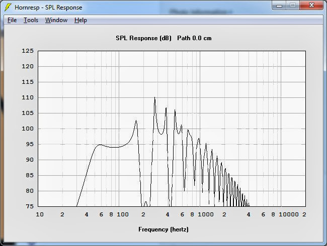
Transmission lines suffer from a nasty dip. In the sim above, we see the dip is occurring at a frequency that's equal to the length of the transmission line.
This dip can be a real deal breaker, and it's one of the reasons that people spend a lot of time 'tweaking' their transmission lines. Here's a short list of things that can be done to address that dip:
1) You can stuff the line. Stuffing the line with insulation reduces the dip. The reason that stuffing works is that the output from the front of the cone is 180 degrees out of phase with the output from the back of the cone, but only at certain frequencies. In the sim above, you can see the dip very clearly at 220hz.
Stuffing the line has a lot of downsides. First, it's hard to simulate. (The behavior of the fibers is very complex.) So when you stuff a transmission line, there's a lot of trial and error involved.
Second, stuffing a transmission line hurts efficiency. You're basically throwing away output. You can see this effect when you compare the efficiency of a transmission line to a tapped horn or an unstuffed back loaded horn.
Last, it often takes a lot of stuffing to make a significant improvement to the dip. The reason for this is that the dip is relatively low in frequency. For instance, in the sim above, the dip is at 220hz. That frequency is over five feet long. Due to that, a lot of dense stuffing is required to make a big improvement, and you can't eliminate it entirely. (Well, technically you CAN but at that point the transmission line is basically behaving like a sealed box.)
2) The second way to address the dip is to taper the line. Tapering the line basically reduces the contribution from the back of the cone. By doing this, you reduce the severity of the dip.
But, again, this isn't an ideal solution. Tapering the line basically gets us closer to a sealed box. So the solution to the dip is also reducing some of the advantages that we were seeking in the first place. (Efficiency in particular.)
3) The third way to address the dip is with the use of a helmholtz resonator. For instance, you can put a helmholtz resonator INSIDE the box, tuned to 'null' out the dip. In this case, you'd have a Helmholtz tuned to 220hz to fix the dip.
This is a solution that can work, but it *also* has drawbacks:
It takes up space, it requires a lot of tweaking, it hurts efficiency, and it doesn't work over a wide bandwidth.
4) The last solution is to simply band limit the transmission line. That works")
But if I was planning on building a subwoofer, I wouldn't have posted this thread in the fullrange forum!
There's gotta be a better way to fix the dip, right?
First, I need to define what a transmission line is.
In a transmission line loudspeaker, the sound from the rear of the cone is transmitted through a quarter wave tube. This is different from a vented box, as a transmission line is only delayed ninety degrees. Some may prefer the sound of a TL to a vented box, due to this aspect.
Transmission lines have a lot of advantages. They have the potential to offer phase response that's superior to a vented box. They give the designer the opportunity to raise efficiency when compared to a sealed box. They are typically smaller than a horn.
There's lots to like - but there's one big problem:
Transmission lines suffer from a nasty dip. In the sim above, we see the dip is occurring at a frequency that's equal to the length of the transmission line.
This dip can be a real deal breaker, and it's one of the reasons that people spend a lot of time 'tweaking' their transmission lines. Here's a short list of things that can be done to address that dip:
1) You can stuff the line. Stuffing the line with insulation reduces the dip. The reason that stuffing works is that the output from the front of the cone is 180 degrees out of phase with the output from the back of the cone, but only at certain frequencies. In the sim above, you can see the dip very clearly at 220hz.
Stuffing the line has a lot of downsides. First, it's hard to simulate. (The behavior of the fibers is very complex.) So when you stuff a transmission line, there's a lot of trial and error involved.
Second, stuffing a transmission line hurts efficiency. You're basically throwing away output. You can see this effect when you compare the efficiency of a transmission line to a tapped horn or an unstuffed back loaded horn.
Last, it often takes a lot of stuffing to make a significant improvement to the dip. The reason for this is that the dip is relatively low in frequency. For instance, in the sim above, the dip is at 220hz. That frequency is over five feet long. Due to that, a lot of dense stuffing is required to make a big improvement, and you can't eliminate it entirely. (Well, technically you CAN but at that point the transmission line is basically behaving like a sealed box.)
2) The second way to address the dip is to taper the line. Tapering the line basically reduces the contribution from the back of the cone. By doing this, you reduce the severity of the dip.
But, again, this isn't an ideal solution. Tapering the line basically gets us closer to a sealed box. So the solution to the dip is also reducing some of the advantages that we were seeking in the first place. (Efficiency in particular.)
3) The third way to address the dip is with the use of a helmholtz resonator. For instance, you can put a helmholtz resonator INSIDE the box, tuned to 'null' out the dip. In this case, you'd have a Helmholtz tuned to 220hz to fix the dip.
This is a solution that can work, but it *also* has drawbacks:
It takes up space, it requires a lot of tweaking, it hurts efficiency, and it doesn't work over a wide bandwidth.
4) The last solution is to simply band limit the transmission line. That works
But if I was planning on building a subwoofer, I wouldn't have posted this thread in the fullrange forum!
There's gotta be a better way to fix the dip, right?
Before I describe the improvement, I wanted to go into some detail on what we're seeing here in hornresp:
1) In the sim, we see that the F3 of the transmission line is basically set by the driver that's in it. In this case, the TL is tuned to the FS of the woofer, which is 51hz.
2) See how there's two lines in the sim? One has a lot of periodic dips; the other does not. The line with all the dips is the output from the cone. The line that's smoother is the combination of the cone and the transmission line. What's happening is that the output from the transmission line 'fills in' the dips. This is particularly noticeable at 110hz.
Of course this is not unique to transmission lines; the dip is also an issue for tapped horns and back loaded horns.
The reason that the dip isn't a problem for vented boxes is that the output from a vent is very narrow; it's just a fraction of an octave.

In the first post I described some of the advantages of transmission lines. They can sound good, because they're phase behavior is potentially superior to a vented box. They're efficient.
But they have a big Achilles Heel - a nasty dip in the response.
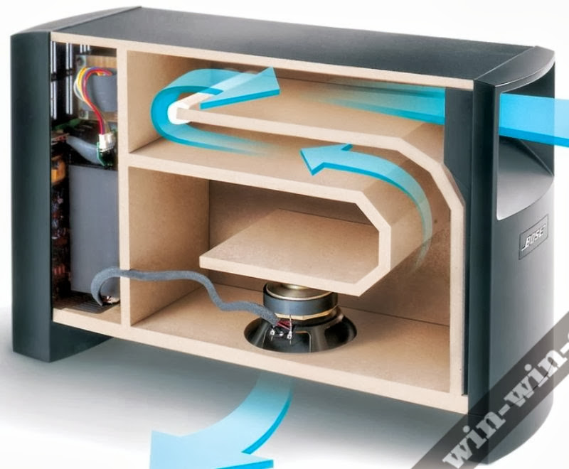
The pic above shows another solution to the problem. The picture shows a short 'stub' that's added to the transmission line. The 'stub' is there for just one reason:
It nukes the dip.
Here's how the stub works:
As noted in the first post, transmission lines suffer from a dip in their frequency response. For instance, when I create a conventional transmission line and I tune it to 50hz, hornresp shows a dip at 220hz.
There's a lot of ways to reduce the dip; I can stuff the box, I can taper the line.
But the stub NUKES the dip.
The way that the stub nukes the dip is that the stub is tuned to the frequency of the dip. So what happens is that a notch is created inside of the transmission line. That notch corresponds to the frequency where we would NORMALLY see the dip.
So basically we get to have our cake and eat it too; we get high efficiency at the low frequencies, thanks to the fact that the front of the cone is being augmented by the output from the transmission line. BUT we also nuke the response from the transmission line at the exact frequency where the cone and the transmission line are 180 degrees out of phase.
In the pic I made the stub blue, to basically illustrate that the stub is a black hole. But only for one frequency. In this case, that frequency is 220hz.
Note that the black hole frequency will depend on your transmission line. For instance, if you scaled this box so that it was a 40hz transmission line, then the stub would likely be tuned to a frequency of approximately 176hz.
Make sense?
Now some might argue that this isn't the only way to do this. And that is true. But I think that the other two ways of doing this do not 'nuke' the dip as effectively.
For instance, you could add a coupling chamber to the transmission line. But a coupling chamber rolls off the output at a rate of six dB/octave. So that means that the coupling chamber is going to roll off our highs a LOT, but it won't have a huge effect on the low frequencies. Of course you could simply use a larger coupling chamber, but then you're making the transmission line larger, more complex, and potentially less sensitive.
A helmholtz resonator could work too; but it's very narrow bandwidth. Might be a good solution if you have the luxury of getting the tuning *exactly* right.
Here's the frequency response of the transmission line pictured in post #3, but without the stub.
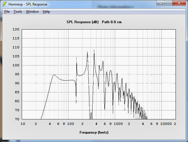
Here's the frequency response of the same transmission line, but WITH the stub. See how the dip at 220hz is filled in now?
In particular, note how the rest of the response curve is unchanged. The hole at 220hz is filled in, but not at the expense of the high frequency output. The 'shape' of the low frequency rolloff has changed, but that is mostly because the line is longer. (IE, you can flatten out the curve by tweaking the line length.)
The bottom line -
The stub 'nukes' the transmission line dip, but not at the expense of efficiency. And the 'stub' is hardly a complex solution; it is not error prone like a helmholtz resonator is.
Last edited:
If anyone would like to try and simulate or build one of these transmission lines, here's some ideas to get you started:
1) The bandwidth will be about two to three octaves. So choose your driver based on what bandwidth you want. For instance, if you need to cover 40hz to 320hz you'd want a driver with an FS of about 56hz.
2) The reason you want a driver with an FS of about 56hz is that the line will be tuned to about .707 multiplied by the FS. For instance, if your driver has an FS of 56hz then you'd tune the line to 40hz. If the driver had an fs of 40hz you'd tune the line to approximately 28hz. You'll want to pop the driver into hornresp and evaluate it that way. Take note of the QTS in particular; a higher QTS value may dictate a lower tuning, and vice versa.
3) I would design the line as a conventional transmission line first. Once I did that, I'd take note of where the dip in the response is. (In the first post, you can see the dip at 220hz.) And once I know where the dip is, then I'd add the stub to absorb it.
Note that this requires the use of an 'offset driver' in hornresp. You can find this under 'tools -> driver arrangement' in hornresp.
Giving credit where credit is due, this is hardly my innovation.
This is the alignment used in the Bose Acoustimass subs.
The measurements and graphs from this thread correspond to the Bose Acoustimass 6 Series III subwoofer. I used the Dayton DC130 as the woofer, as it's about the right size and the right FS.
The dimensions should be very close; I measured them carefully. So this should be a fairly accurate prediction of how the sub performs.
My hunch is that the transmission line from Bose is designed to address some of the shortcomings with the older Acoustimass subs. The older subs used a triple chamber bandpass design. I made a model of that design in Akabak, and my model indicates that the triple bandpass alignment has high efficiency, but narrow bandwidth. It's good for about one, maybe one and a half octaves. That creates a problem for Bose's customers; it means that there's going to be a 'hole' in the response between the subwoofer and the satellites.
The transmission line addresses that; it should have bandwidth that's significantly wider.
The official terminology for the stub is driver offset, Zd. With correct offset you can almost eliminate the 1st unwanted harmonic. This is well understood and was first described by Martin King over 10 years ago. BTW, Martin's software does a pretty good job of simulation the damping, and is a more intuitive tool for developing TLs.
dave
dave
The official terminology for the stub is driver offset, Zd. With correct offset you can almost eliminate the 1st unwanted harmonic. This is well understood and was first described by Martin King over 10 years ago. BTW, Martin's software does a pretty good job of simulation the damping, and is a more intuitive tool for developing TLs.
dave
Interesting!
Like most people do, I typically take a 'trial and error' approach to hornresp, and generally optimize for flat low frequency response.
The thing that was intriguing about the Acoustimass is that the woofer offset is quite large!

Here's a clone of a TH-Mini tapped horn, along with the Acoustimass; the TH-Mini has nearly zero offset.

Interestingly, it appears that the TH-Spud uses a lot of offset, along with a slow taper, similar to the acoustimass. I'll have to run some sims on the TH-Spud and see if that offset is tuned to the first dip. Perhaps that explains why the TH-Spud has relatively low efficiency, but wide bandwidth? Whereas the TH-Mini has high efficiency and *low* bandwidth?
(Just thinking out loud here.)
Hi,
As others have said its just driver offset and near 1/3 along the
line was a rule of thumb years before MJK got involved in the act.
An old school TL side on would have 3 sections, gap at the front
gap at the rear and exit at the top. Placing the driver near the
top at the front placed it about 1/3 along, usually a bit less.
Old school was also 2 sections, gap at the top, exit at the
bottom, expanding tapered driver on the front (or rear),
usually a truncated narrow section to get nearer 1/3.
Then Bud Fried came along with a load of unverified nonsense,
but he made it sound good, which it isn't, and was very influential.
MJK's stuff is far more rigourous, and far nearer the truth.
rgds, sreten.
Last edited:
There are many options to tune a TL. Reactive filter approach for me the most efficient one, if for example compared to the approach in which the designer fills the cross-section of the line with damping material or even worse, adding a mass loading at the exit of the line.
The reactive filters are solid structures and they do not change properties with increased volume levels. In the case of filling material, they start to move with relative to the air particles, therefore the friction gets smaller and they loose functionality. In the case of mass loading, the friction around the sudden cross-section change also introduces a non-linear behavior, which also changes with the increased volume velocity.
Reactive filters, like resonators, band pass filters or placing the loudspeaker at a certain ratio of the line is a robust design. One can create a low-pass filter in the line to eliminate the unwanted resonances above the fundamental or just kill the second harmonic in high accuracy. Some even tries to kill the third one, because once it is achieved, also the second harmonic gets attenuated. Yet, although the names differ, the application of these can be seen from the very early days of the TL designs. Even in the text of Beraneck he talks about in line low-pass filters and notch filters.
I believe the Germans like to implement Helmholtz tuned cavities to null out the main peaks at 3rd and 5ths. An offset between these points serves a similar purpose.
Much like Visatons kit 'vib130tl' which inspired my own TQWT based on MJKs alignment tables and honed with PeteMcks helpful mathcad checking of my initial work. Except in that i omitted any resonant chambers and used an offset instead.
A real TL still has its charm to me, aside from the sealed box comparisons, the reduced pressure box effect and tamer impedance plot are almost unique to conventional dynamic speaker systems.
How great the advantage depends on perspective though, i guess.
P.s.
The bose offset looks like a ballpark 3rd line length, if you ask me, and id bet it was between 1/3 and 1/5 and following the old school rule.
Last edited:
The bose offset looks like a ballpark 3rd line length, if you ask me, and id bet it was between 1/3 and 1/5
Very good guess, in fact the offset is 1/4 exactly. Certainly driver offset effects standing waves, but here that is not what is intended. Here, the offset is to modify the amplitude and phase relationship of the two combined pressure waves, one from direct radiation from the driver, and the other from the transmission line terminus. The null effect is caused by the "adding" of pressure waves that are in phase opposition. The OP is on the right track, and there is more than one way to skin this cat.
refer to: U.S. Pat. 7426280
Regards
I can recommend MJK´s models.
From MJK´s excellent work you can model different geometries, volume, tuning frequency, stuffing, driver offset – all the parameters that has an impact on the final result.
My own rules of thumbs are:
Driver offset 1/5.
Tuning 10 to 20 Hz below driver Fs depending on Qts.
For driver with Qts below 0.30 set the tuning higher than driver Fs.
Stuffing upper 2/3 of the line.
Use a straight line, with the last / part having a smaller cross section.
Hi from
Bjørn
Yes, Martin King's work is great, and it is cool to see people doing simulations too.
The reason I posted here is that I seen a topic that I have not seen discussed. That is, the interference nulls created with transmission line type speakers. It is the same effect that causes the combing with a center mounted driver on a circular open baffle. Bose worked on this problem and has at least two patents that deal with it each differently.
U.S. Pat. 7426280 and 6771787.
One of the patents uses a driver offset to create a "1/4 wave stub filter" that eliminates the offending frequency(s) from radiating from the terminus.
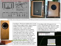
Onken tech resonant-tuned bottom slot ported MLTL "Onken-on-the-floor"
Q: Could Onken type narrow multi-slot ports on the bottom of a TL be used to remove MLTL upper resonant harmonics, as a technology solution to reduce cabinet volume and stuffing requirements? Narrow, tuned, Onken slot ports designed to attenuate the quarter-wave second, fourth, eight harmonics in order to reduce T-line size but keep efficiency. Locating the driver slightly less than 33% down from the cabinet top reduces third, fifth, seventh odd harmonics to complement the Onken slot ports.
Gene Higara Altec 604 appears to use narrow tuned Onken type slot ports on the bottom of the quarter-wave bass reflex cabinet to reduce midrange resonances without excessive MLTL stuffing that also reduces SPL.
Jean Hiagra on his 604 cabinet design:
"The chosen solution here accepts a load of much smaller speaker volume (around 190 liters, instead of the usual 350 liters required for a 15 in. woofer) without experiencing a sharp decrease in sensitivity over the low frequencies, none of the usual sound colorations when a large woofer is associated with a load of small volume. This goal has been reached successfully thanks to the merging of several means : no back-chamber/throat (decompression) but a tuned load (BR) thanks to a laminar vent situated under the speaker itself, to adequate filters and, finally, proper internal padding on wooden walls made of an optimized sandwich of wool plies.”
Attachments
Q: Could Onken type narrow multi-slot ports on the bottom of a TL be used
I don't know if it does what you suggest, but we have implemented a number of Dr. Lindgren ML-TLs with such vents. They worked out really well.
dave
- Home
- Loudspeakers
- Full Range
- An Improved Transmission Line Alignment