Love your design
I liked so much Im going to build it ,but Im going to cut down on the labor. my man I appreciate your dedication and drive on this project because Im into wood also and know the eminence work you put into these. Im going to cut out my top and bottom then the 2 side pieces that I will take and score a 1/2 " deep ever 1/4" along the length lipping it the top , bottom and front. fill in the scores with glue then wrap around the top and bottom as these will become your formers, tacking then in place with a brad tacker while the glue dries. this will give the same appearance and you add bracing as required..... Great looking speaker though
I liked so much Im going to build it ,but Im going to cut down on the labor. my man I appreciate your dedication and drive on this project because Im into wood also and know the eminence work you put into these. Im going to cut out my top and bottom then the 2 side pieces that I will take and score a 1/2 " deep ever 1/4" along the length lipping it the top , bottom and front. fill in the scores with glue then wrap around the top and bottom as these will become your formers, tacking then in place with a brad tacker while the glue dries. this will give the same appearance and you add bracing as required..... Great looking speaker though
kinda sounds like homemade kerf-core, wrapped around the curved top/bottom & braces with slots filled with glue?
If so, note that a standard width blade kerf at 90dg severely limits your radius - and also note it gets a lot harder to add bracing to the inside of a curved fabrication afterwards.\
If not, then yes, some sketches or progress photos would be helpful for us newbies to learn the process
If so, note that a standard width blade kerf at 90dg severely limits your radius - and also note it gets a lot harder to add bracing to the inside of a curved fabrication afterwards.\
If not, then yes, some sketches or progress photos would be helpful for us newbies to learn the process
Thanks,
I cannot totally picture what you're saying here but I think I get the general idea.
Hope you make pictures along the way to show your progress!
Here take a look at this how to kerf, Kerfing MDF, Bending Wood - YouTube
how to kerf, Kerfing MDF, Bending Wood - YouTubeI liked so much Im going to build it ,but Im going to cut down on the labor. my man I appreciate your dedication and drive on this project because Im into wood also and know the eminence work you put into these. Im going to cut out my top and bottom then the 2 side pieces that I will take and score a 1/2 " deep ever 1/4" along the length lipping it the top , bottom and front. fill in the scores with glue then wrap around the top and bottom as these will become your formers, tacking then in place with a brad tacker while the glue dries. this will give the same appearance and you add bracing as required..... Great looking speaker though
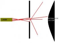
diffraction
I didn't want to go to an all aluminum enclosure but figured a baffle made from aluminum could have it's plusses. I would use one plate before the drivers with the fillet wave guide like shape and use another plate behind the drivers to mount them.
Something like this: Can you explain how you eliminate diffraction with rear mounted speaker's #1- then # 2 radius the opening ? two known areas that cause diffraction.... this the main reason modern speaker manufactures inlay-surface mount to eliminate as much diffraction as possible . Am I missing something here?

The open spaces behind the back plate and in between the two aluminum plates could be filled with mass loaded vinyl. A heavy acoustic rubber, in my mind serving to dampen the aluminum baffle while making it more sound proof.
Attachments
Last edited:
I am just trying to smooth out the transition of the cone to baffle with that radius.
The radius will act somewhat like a wave guide. If you mount the speaker flush, you'd still have the surround sticking out, unless its inverted. I tried to make the transition as smooth as possible between cone, surround and baffle.
It won't be ideal as it will always have the surround.
Looking up the FR plot of a Vifa back-mounted with a radius seemed to improve off axis response till 15 degrees and flatten the on axis response: ViFAST - für 50Euronen (SDS 5 1/4 + Vifa 9 BN 119/8) **fertig! Weiche S.3** - DIY-HIFI-Forum
Worth a try for me, the inset is 9 mm in that example and I use a similar radius on a thinner front baffle (6 mm thickness) to be somewhat in-between.

I can't tell you if it works, time will tell.
The radius will act somewhat like a wave guide. If you mount the speaker flush, you'd still have the surround sticking out, unless its inverted. I tried to make the transition as smooth as possible between cone, surround and baffle.
It won't be ideal as it will always have the surround.
Looking up the FR plot of a Vifa back-mounted with a radius seemed to improve off axis response till 15 degrees and flatten the on axis response: ViFAST - für 50Euronen (SDS 5 1/4 + Vifa 9 BN 119/8) **fertig! Weiche S.3** - DIY-HIFI-Forum
Worth a try for me, the inset is 9 mm in that example and I use a similar radius on a thinner front baffle (6 mm thickness) to be somewhat in-between.
I can't tell you if it works, time will tell.
Last edited:

I truly hope it works for the time and money you have invested in this baffle. But the subject of speaker diffraction by most speaker builders is to decrease surface area to eliminate areas for diffraction to take place ,meaning any area in front of the speaker even a curved surface will reflect sound wave. The diagram I posted shows this idea. I truly hope your testing proves this theory wrong because I think your baffle design is cleaner looking than a front mount approach... Keep us posted on your progress ....
I guess it will take some tome before I know anything. I am waiting for spring before I can do what I want with my enclosures. Maybe I'll have some results before that though but I'm not counting on that.
A quicker way would be to ask member Koldby for some measurements:
http://www.diyaudio.com/forums/multi-way/193015-stupid-cheap-line-array-21.html#post2890230
That array changed my mind in how I wanted to mount my drivers...
A quicker way would be to ask member Koldby for some measurements:
http://www.diyaudio.com/forums/multi-way/193015-stupid-cheap-line-array-21.html#post2890230
That array changed my mind in how I wanted to mount my drivers...
Those bezels with a radiused edge act as a very short horn. Probably won't affect upper freq response much but may change the dispersion somewhat (anything placed on front side of driver affects the directivity and response. ) I can simulate that effect for you if you want - get me the depth and radius of the fillet you are using.
The front mounted plate is 6mm thick with a 8mm radius. I am sure it will change the response some, acting as a waveguide/horn. But the end result will be shaped with EQ to compensate. I'm hoping to see some of the effects as in that link I posted to that german FAST build using the Vifa. The radius and thickness was 9mm on that one but it straightened the on axis response and made it closer to the 15 deg off axis plot.
But the end result will be shaped with EQ to compensate.
Avoiding discontinuities seems to be the big lesson in the various arguments on horns. (Eg. Beyond the Ariel).
Discontinuities cause reflections which result discrete time delays - these result in comb filtering.
You can't EQ these away
I have those TC9FD drivers rear mounted in little 1/2 inch MDF cabinets I built, with the horn curve hole just like in your pictures. I haven't done any calibrated mic measurements, but they sound very good to my ear.
I would expect a calibrated mic might show a small amount of ripple in the frequency response due to diffraction effects, and a slight narrowing of the dispersion at high frequencies, but nothing major.
Because the magnet on those drivers is large diameter, relative to baffle hole size, the rear airflow for these TC9 drivers is something that should get special attention. Because of this, it's not necessarily desirable to front mount these drivers on a baffle board thicker than 3/8 inch, even with the horn hole routering on the back side. Using approximately 1/4 inch aluminum baffle panel seems like a great way to help that effort, if the aluminum is damped properly (if internal shelves attach to it, there should be no problem with damping).
Personally I'd front mount the drivers (for best off axis dispersion, and in case you ever need to replace a single driver), but rear mount may work virtually as good acoustically.
Last edited:
The front mounted plate is 6mm thick with a 8mm radius. I am sure it will change the response some, acting as a waveguide/horn. But the end result will be shaped with EQ to compensate. I'm hoping to see some of the effects as in that link I posted to that german FAST build using the Vifa. The radius and thickness was 9mm on that one but it straightened the on axis response and made it closer to the 15 deg off axis plot.
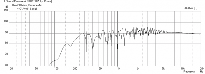
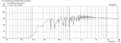
I did not do the simulation for a 25 driver array but I put the bezel on the Nautaloss II (dual drivers). The difference is almost negligible - it seems to actually boost the HF by a tiny bit on axis. I modeled the bezel as an exponential waveguide starting with an area equal to Sd (36.7 cm2) and expanding to 55.4 cm2 (a 0.8 cm radius increase for the mouth area) over 6 mm length.
Here are the frequency response plots (with room reflections turned on) for no bezel and with bezel.
Attachments
Avoiding discontinuities seems to be the big lesson in the various arguments on horns. (Eg. Beyond the Ariel).
Discontinuities cause reflections which result discrete time delays - these result in comb filtering.
You can't EQ these away
True, that's why I looked into the radius backside mount solution. Did you compare the plots on that German site? There is less of a difference in the on axis / off axis plots with the back side mount plus radius compared to the flush mounted driver. The part that needs EQ is the slight boost the horn/waveguide shape gives.
True, that's why I looked into the radius backside mount solution.
I'm glad to see that you are "all over it" (as we say ).
- Home
- Loudspeakers
- Full Range
- The making of: The Two Towers (a 25 driver Full Range line array)